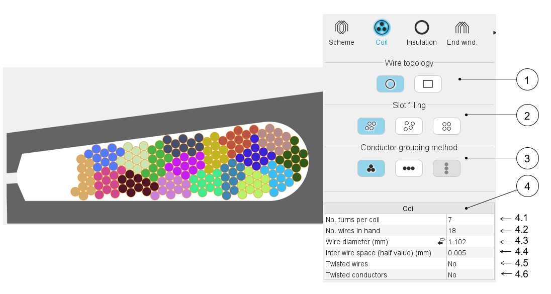
Coil
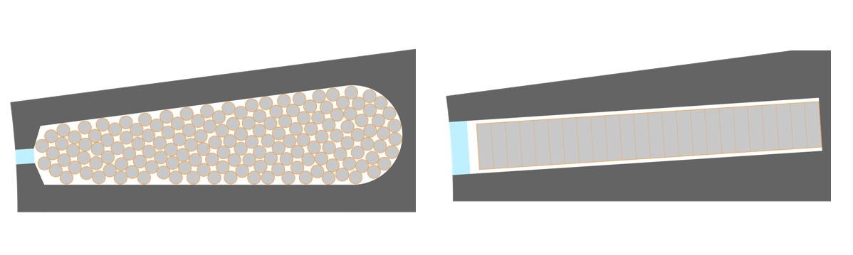
Case of circular wires
 |
|
|---|---|
| 1 | Definition of the wire topology, Circular or Rectangular |
| 2 | Choice of the method to fill the slot: Three ways are allowed to fill the slot: Orthocyclic, Random, Layer. See the below illustrations. |
| 3 | Choice of method to group the elementary wires. Three ways allow to fill the slot: Grouped, Horizontal, Vertical. See the below illustrations. |
| 4 | Description of the coil and dimensions of elementary wires + twist options. |
| 4.1 | Number of turns per coil |
| 4.2 | Number of wires in parallel in a conductor (per turn), i.e. number of wires in parallel in each conductor. |
| 4.3 | Wire diameter (without insulation), for circular wire (1) |
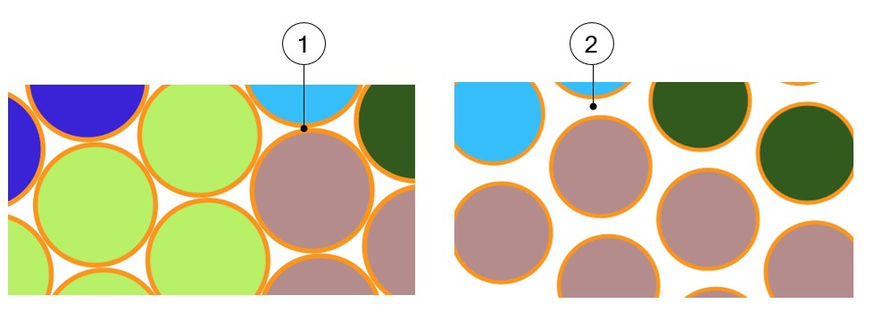
| 4.4 | Minimum distance between insulated wires to be considered for
modeling inside the Altair Flux 2D
environment. When there is no wire insulation, Inter-wire space represents the minimum distance between the bar wires (2). |
| 4.5 | The wires can be twisted inside the conductor. |
| 4.6 | The conductors can be twisted inside the slot. |
- Directly entering the value of the wire diameter (without insulation).
- Choose the diameter from the American Wire Gauge table in which available wire diameters are listed (without insulation).
- Choose the diameter from the Metric Wire Gauge table in which available wire diameters are listed (without insulation).
This value is considered in Motor factory for computing the filling factor and while exporting a model into Altair Flux environment (Export area) for building the corresponding finite element model.
 |
|
|---|---|
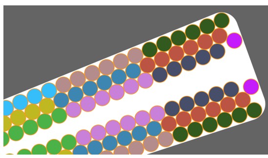
| 1 | Default value for inter-wire space and the corresponding pictorial display. |
| 2 | Impact of a higher value for inter-wire space |
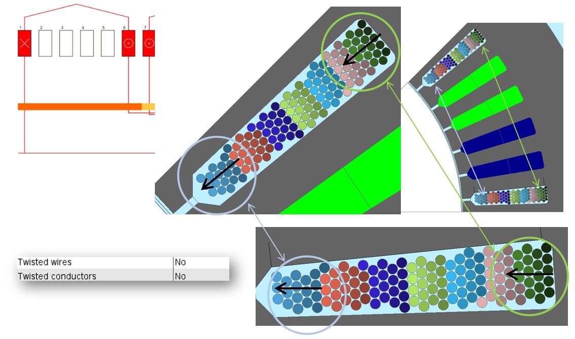
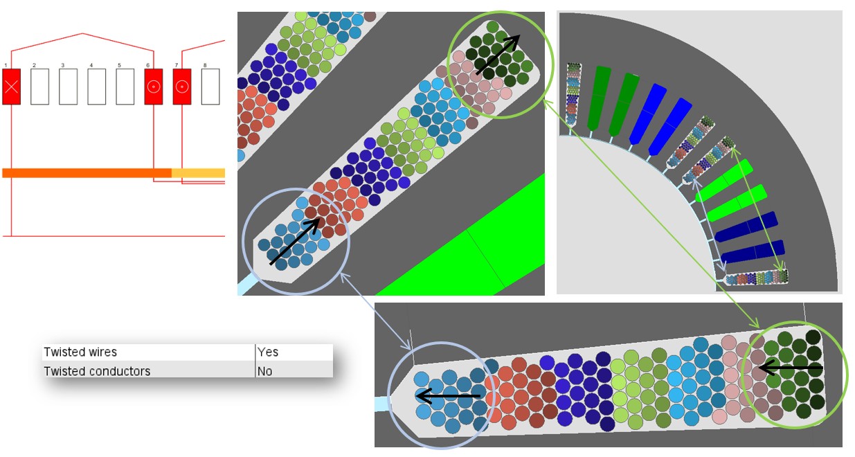
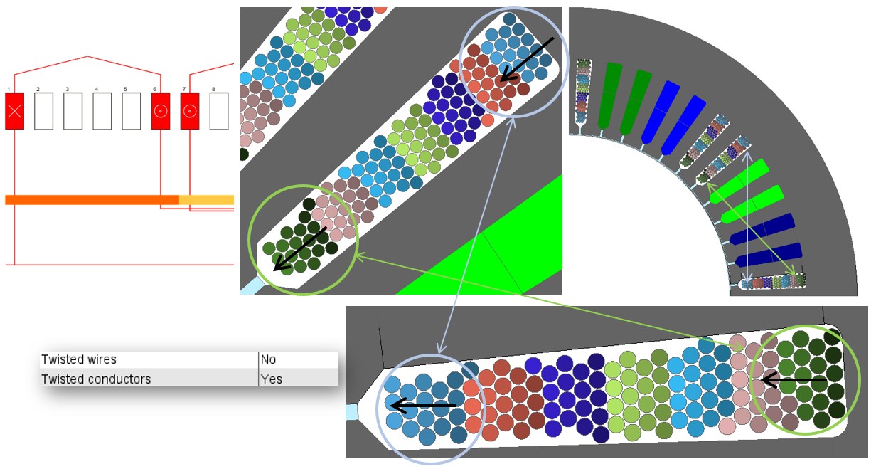
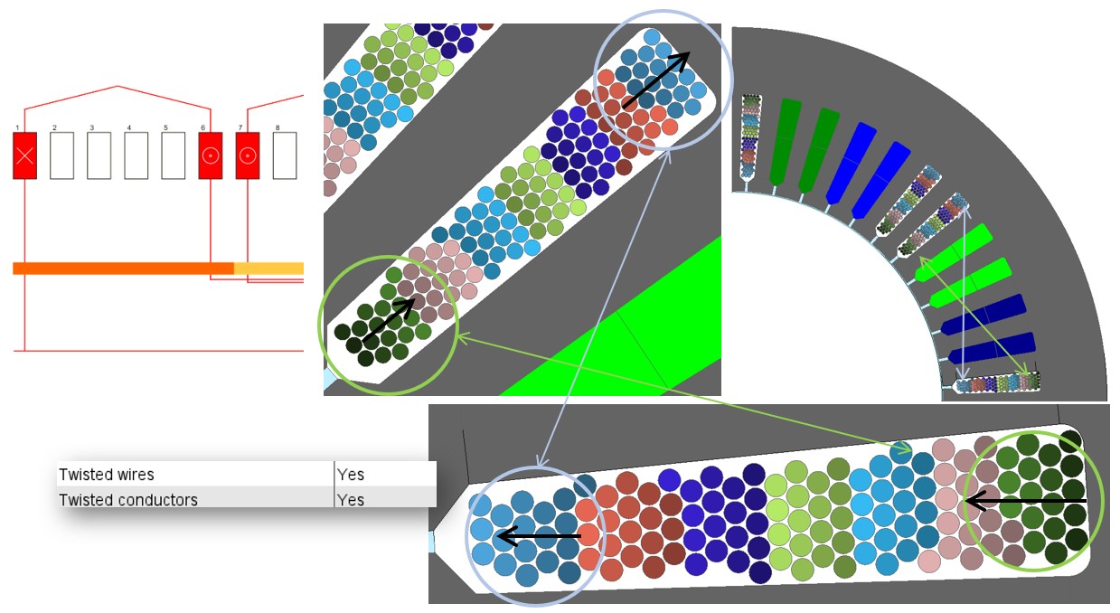
While defining the coil in the design / Winding area, it is possible to twist the wires inside the conductors between the forward and return sections of the coil. It is also possible to twist the conductors between the forward and return sections of the coil.
It is possible to twist both the wires inside the coil and the conductors between the forward and return sections of the coil.
The four illustrations of what it is possible to do are presented below.
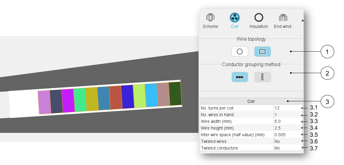
Case of rectangular wires
 |
|
|---|---|
| 1 | Definition of the wire topology, Circular or Rectangular |
| 2 | Choice of the method to group the elementary wires. Two ways allow to fill the slot: Horizontal and Vertical. See the next sections which illustrate the grouping methods. |
| 3 | Description of the coil and dimensions of elementary wires + twist options. |
| 3.1 | Number of turns per coil |
| 3.2 | Number of wires in parallel in a conductor (per turn), i.e., number of wires in parallel in each conductor. |
| 3.3 | Wire width (without insulation), for rectangular shape type wire. |
| 3.4 | Wire height (without insulation), for rectangular shape type wire. |
| 3.5 | Minimum distance between insulated wires to be considered for
modeling inside the Flux® 2D environment. When there is no wire insulation, Inter-wire space represents the minimum distance between the bar wires. |
| 3.6 | The wires can be twisted inside the conductor. |
| 3.7 | The conductors can be twisted inside the slot. |
Explanation about the different ways to choose the wire diameter, the inter-wire space and the twisted conductors and wires are presented in the section dedicated to the circular wires.
Relevance of the slot filling
When the number of wires is higher than allowed by the free space of the slot, the wires are grayed. This is to inform the user that the number of wires must be decreased.
In that case, the design of the winding is not possible; the machine cannot be built or tested.
Motor Factory Design environment icon and winding icon in the Stator section are colored in red. This means that a design fault exists and must be corrected in the winding section of the design environment.
The tests cannot be performed; the tooltip message indicates that the slot filling is not valid and that the user must modify the slot filling parameters to unlock the test.
At the same time, a warning message indicates that there is not enough space for the specified number of wires. The allowed number of wires is mentioned in comparison with the targeted ones.
Slot filling illustrations
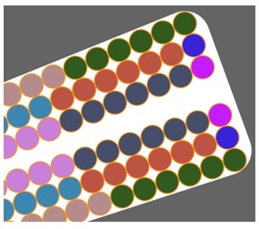
Illustrations with the circular shape type wire
 |
 |
 |
|---|---|---|
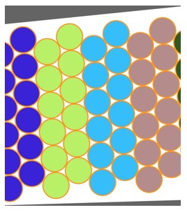
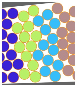
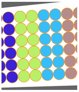
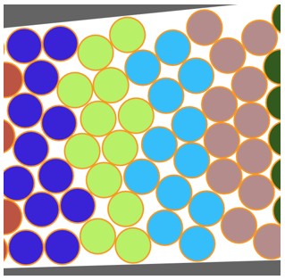
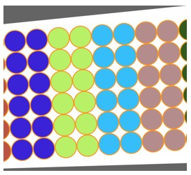
| Orthocyclic slot filling | Random slot filling | Layer slot filling |
Conductor grouping method
- Illustrations with circular shape type wire
- Case 1 – With an Orthocyclic slot filling
Table 5. Case 1 – With an Orthocyclic slot filling 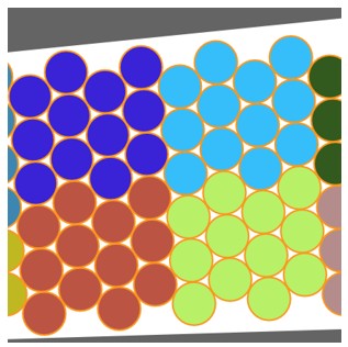
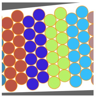
Grouped filling Horizontal filling Vertical filling (1) - Case 2 – With a random slot filling
Table 6. Case 2 – With a random slot filling 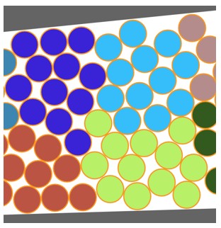
Grouped filling Horizontal filling Vertical filling (1) - Case 3 – With a layer slot filling
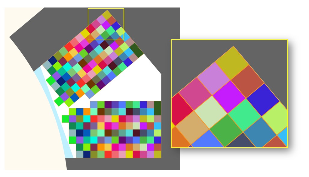
Table 7. Case 3 – With a layer slot filling 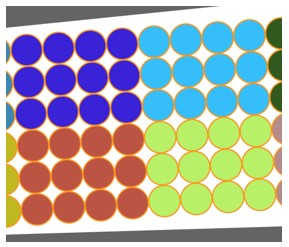
Grouped filling Horizontal filling Vertical filling (1)
Note: (1) Vertical filling is only available for tooth windings (i.e. when the coil pitch = 1). - Case 1 – With an Orthocyclic slot filling
- Illustrations with circular shape type wire
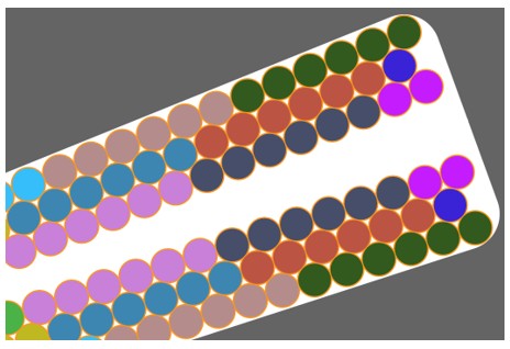
- Example 1
Figure 7. Horizontal filling 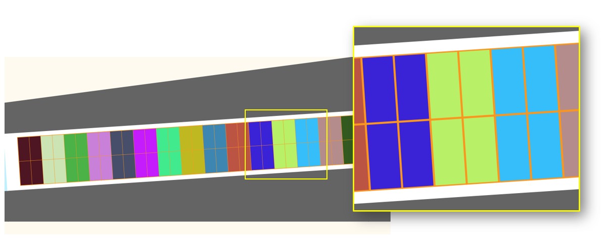
Note: Vertical filling is only available for tooth windings (i.e. when the coil pitch = 1). - Example 2 with a tooth winding (i.e. the coil pitch = 1)
Table 8. 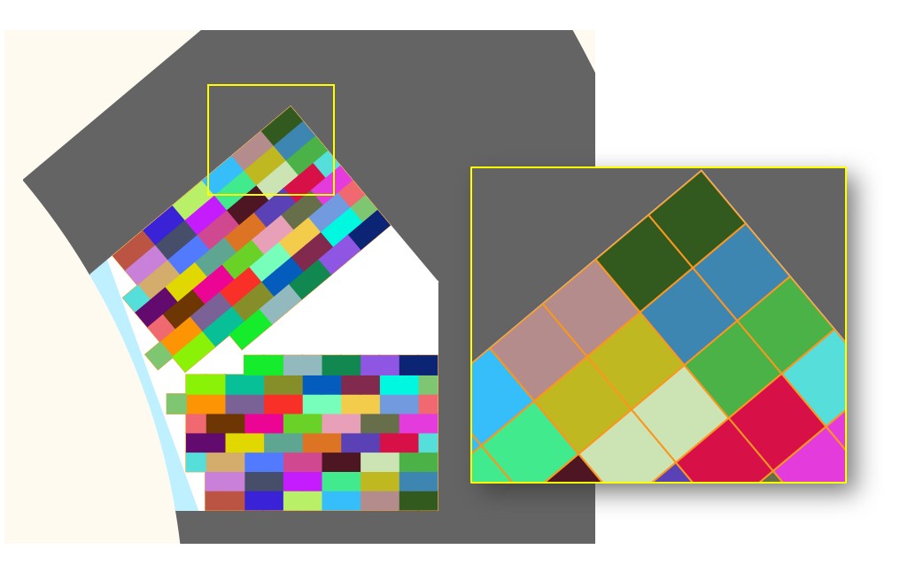
Horizontal filling Vertical filling (1) Note: (1) Vertical filling is only available for tooth windings (i.e. when the coil pitch = 1)
- Example 1