Cut objects
Introduction
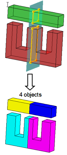
The geometric operation s allows cutting one or more objects as a reference plane in two steps:
- Detection of cut section: intersection between objects to cut and reference plane passing through these objects
- Choice sections to cut
Structure of cut objects
The operation Cut objects is describe by a wizard in two steps:
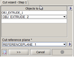
- Step 1: Detection of cut sections
- The list of objects to cut
- The reference plane taking into account in the detection of intersections with selected objects
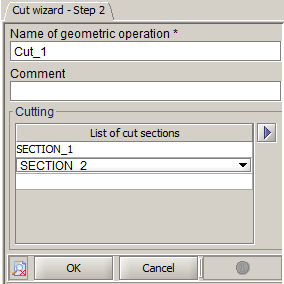
- Step 2: Choice of sections to cut
- The list of sections taking into account for the cutting
| Dialog box | Illustration |
|---|---|
|
Step 1 « Detection of cut sections »
|
|
|
Step 2« Choice of sections to cut »
|
Result
The application of a cutting of objects has as result:
- N resulting cut objects following the number of cut sections and the number of closed contours (OBJ_CUT_1, OBJ_CUT_2, …OBJ_CUT_N).
- A geometric operation CUT_1. This geometric operation is a specific entity of the modeler that permits to ensure the cycle of life of the construction (creation - modification - deletion).
- N geometric operations corresponding to the creation of each object (CUT_1_1, CUT_1_2, …, CUT_1_N)
- The operation CUT_1 has been added in each geometric operation list linked with each object OBJ_CUT_1, OBJ_CUT_2, …OBJ_CUT_N
- Each geometric operation (CUT_1_1, CUT_1_2, …, CUT_1_N) is respectively added in the list of geometric operations linked with each corresponding object (OBJ_CUT_1, OBJ_CUT_2, …OBJ_CUT_N)
Then the user may delete objects that he wishes.
Access
The different accesses of the geometric operation Cut objects are:
- By menu:
- By icon:

When use the cut operation
The operation of cut objects can be used:
- To reduce a geometry (built in the modeler or after an CAO import) taking into account symmetries / periodicities and thus reduce the mesh and so reduce the solving time.
- To delete some parts of the geometry after an import, which are not necessary to the modeling
Creation of cut objects
The process of creation of a cut objects is presented in the table below.
| Phase | Description | Wizard |
|---|---|---|
| 1 | Opening the dialog box Cut wizard | _ |
| 2 | Choice objects to cut | Step 1 |
| 3 | Choice reference plane to the detection of cut sections | |
| 4 | Validation of the first step and passing at the following step by clicking on >> | |
| 5 |
Choice of name of the geometric operation resulting (by default : CUT_1) |
Step 2 |
| 6 | Validation by clicking on OK | |
| 7 | For example, delete objects to do disappear | _ |
Limitations
Some limitations :
- The geometric operation Cut objects is not modifiable. In this case, the user must delete in force the geometric operation of cut and create again with the wished modifications.