Altair Flow Simulator 20.1 Release Notes
New Features & Enhancements - 20.1 Production Release
Graphical User Interface (GUI) Capabilities & Improvements
-
Chart Features: Flow Simulator plotting capabilities have been improved and new capabilities have been added. The new feature can be found at PostProcessing → Results Table with a name of “Create Plot” or with a right click on the results table. Once, users click on Create Plot, all plotting activities will be done through a new window. For all plot types (plotting steady-state analysis results, multi-case analysis results and transient analysis results) users are now allowed to plot each result on a new chart window or multiple results on the same chart window. On the Create Plot Window, the selected results (properties, inputs, and variables) are listed in Y-Axis drop down menu and X-Axis can be Object IDs for Steady-State analysis results, Case IDs or Multi-Case Properties for Multi-Case analysis results and Time for Transient analysis results. Once the plots created, on the chart window with a right click, the feature now enable to edit the plot, to zoom in/out, to reset zoom and to show/hide the legend(s). The Edit Axis option enables to change bounds of the Y-Axis and X-Axis (if x-axis is Time), add/remove/arrange Minor and Major grid lines and font size of the legends, titles and axes titles and numbers.
-
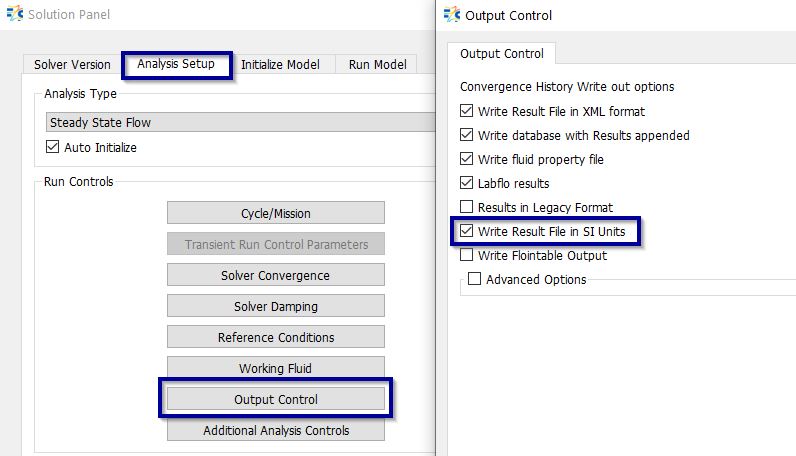
write .res file in SI UNIT System: Options are provided for users to write .res file in SI UNIT System. Under Output control users can enable this option as shown below. This option gets automatically checks in, if users prefer to work in SI unit system for GUI using Unit Maintenance options
-
Legend Updates: Contour and Transient Animation features have improved in Flow Simulator. Users can see the results of their model analysis on the Flow model as colored contours or as a time animation for transient analysis. Contour and Transient Animation features can be found under PostProcessing section. Contour Coloring feature enables users to colorize the model objects based on the initial data or analysis results. Moreover, users can see how their transient analysis results change with time using the Animation feature. Legend Widget is common for both features. The settings enable to select the type, position and coloring style of the legend, to change numeric precision, numeric font and number of levels of color bar, to add/remove header, footer and title, and moreover, it is possible to show/hide minimum and maximum values with object IDs.
-
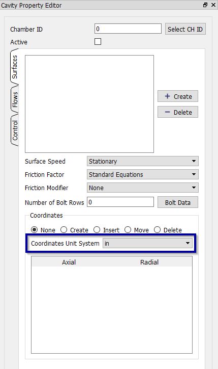
Cavity Surface coordinates unit system updates – Flow Simulator is Unitless, so its user’s responsibility to ensure correct unit system while picking Cavity surface coordinates from screen. Options has been enabled to select coordinate unit system for picking surface points from screen.
-
Cavity Surface points can be created from Iges. The vertex on Iges are enabled for pickup through cavity property surface create options
-
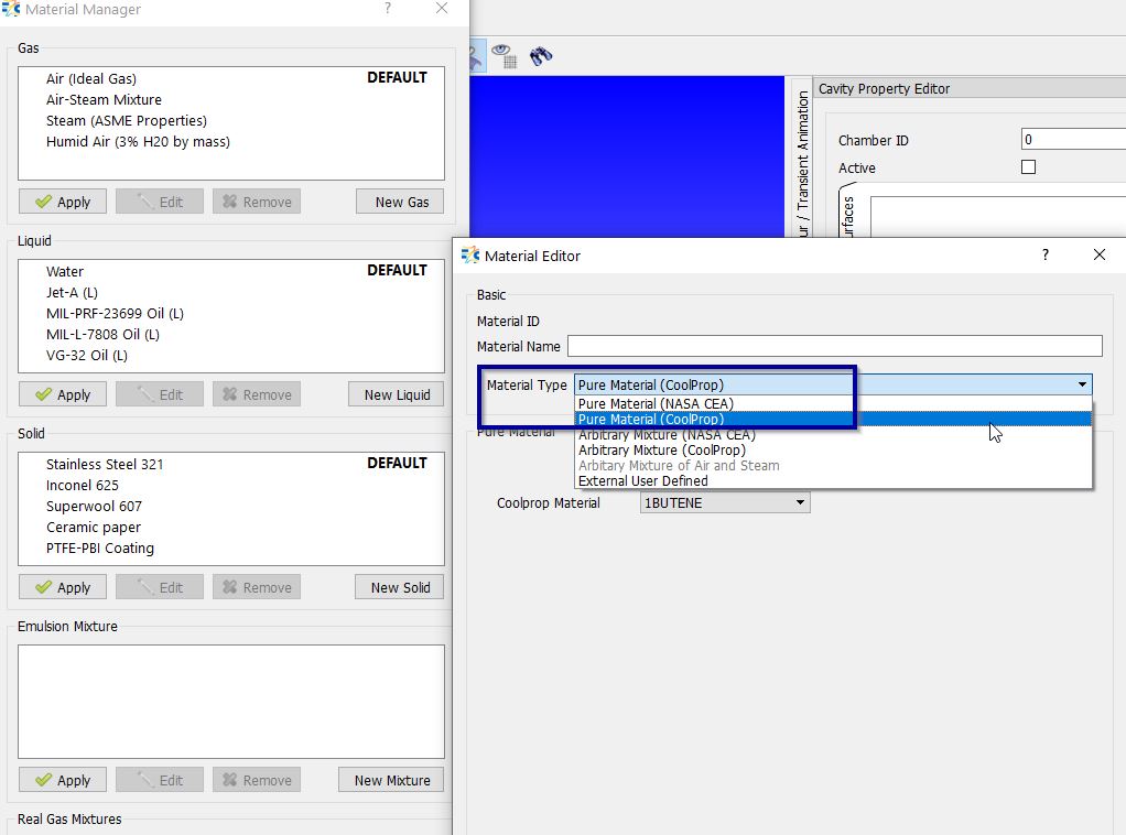
New Material database has been introduced (CoolProp). Users will have both NASA CEA & CoolProp for selection to create user defined materials. More reference to CoolProp are available at http://www.coolprop.org/
-
Import/Export of User Defined Materials are enabled, users can now import and export the user defined materials across models & across users.
-
“.Stp file format is supported along with IGES for CAD options
-
Cad Integration features are available now. Users can create automatic flow models from CAD using this option.
- After Importing the CAD, users can right click faces on the CAD & click crate element to add the element.
- Currently Tubes, Bends, Junctions, Transitions are enabled for automatic creation
- Detailed Help are available under “GUI- Geometry Panel” Section
Available operations on CAD geometry:
- Insert Vertices & Save them for further operations
- At end points
- At the center
- Distribute vertices based on either number of vertices or distance between the vertices
- Insert Lines
- Measure distance & area between the imported and/or inserted CAD vertices
-
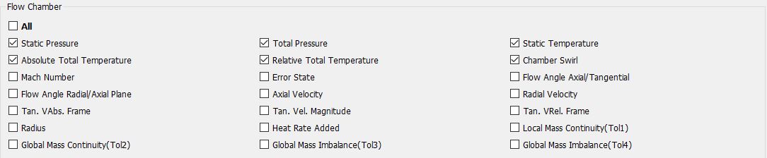
Result variables in display settings are enabled for all chamber variables. Some of the key new additions are Static Temperature, absolute & relative temperature, Error States, Radius Velocity, etc.
-
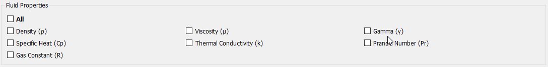
On screen display for Fluid Properties are enabled in addition to loading the flow & thermal results. Users can control the same under display settings.
-
Results Table Updates (Sorting Options & Querying): Results Table feature enables users to list the results of all objects’ properties after the analysis. New capabilities have been introduced in Results Table feature. Now, users can sort the selected objects in Ascending, Descending order based on their IDs, X-locations, Y-locations and Z-locations, or in User Selection order with comma between the object IDs.
-
Results Querying for Output Variables has been added under Results Table.
-
Thermal Network Entities has been added under Results Table query (Pick Options)
-
Groups Updates: Groups feature has been reorganized in this release. The Hide/Show/Isolate buttons moved to left side of the group names so that all the group names and the buttons will be inline. New capabilities such as changing the font of the group name to Bold if it is isolated or Grayed if it is hidden, sorting the objects in ascending or descending order under the group names & Group Multi selections are enabled.
-
A brand-new feature of Tube/Pipe Property Plotting feature has been introduced in Flow Simulator. This feature enables users to plot the Station (and Circumferential Segment for incompressible tube and advanced orifice) based results of all Tube/Pipe elements (incompressible and compressible) and Advanced Orifice element. Similar to Chart Feature, users can plot steady state analysis results of selected tube/pipe/advanced orifice at each Station, Segment or X-Location, multicase analysis results and transient analysis results of selected objects’ selected station, segment or X-location at each case, and at each time point, respectively.
-
Elastic Pipes are now available under tube section to study water hammer analysis.
-
4-Arm UDE: New UDE element has been introduced in Flow Simulator. 4-Arm UDE element is added to represent Heat Exchanger element and bring flexibility for the users to define their equations. The usage of the 4-Arm UDE is same with predefined UDEs, except, now users must connect 4-Arm UDE to 4 chambers. Similar to the Heat Exchanger component, there will not be any mixing option in 4-Arm UDE for now.
- New Elements & Components have been added.
- Link Element

- Turbine Element

-
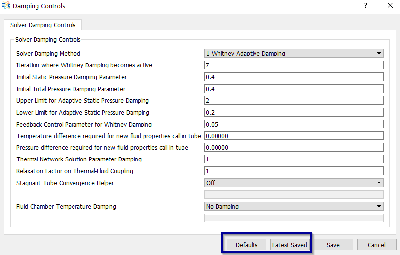
“Defaults” & “Last Saved” options have been added to Solver Convergence & Solver Damping panels
-
Vortex Chamber updates – Options to switch from vortex to inertial chambers are enabled.
-
User can specify Results Folder Name of their interest. The results folder name will be appended with time stamp. The Format is “UserDefinedFolderName_dd-mm-yyyy_hh-mm-ss”.
-
New options are added in Fans & Compressor element for pressure rise methods (Ptup-Ptdn)
-
Reference density option are provided for Louver elements
-
New Help Document architecture is released with all new features for Flow Simulator GUI & Solver. Documentation link has been created between GUI and Documentation for all panels & Property editors
Solver Capabilities & Improvements
-
Linux Version of Flow Simulator solver is available. Can be used to launch multiple Flow Simulator runs in Linux environment
-
Junction element robustness and speed has been tremendously improved. Speed improvements most noticeable for models using NASA CEA fluid properties, but other models should also have some speed improvement. Robustness improvements benefit convergence for most model & for more stable predictions. Added check to make sure elements attached to junctions have consistent area with junction arms (improves convergence). Warning written to convhist_fi.out.
-
SI units are now available in output files. The English based units are still the default, but SI units can be written by setting Analysis Setup → Output Control → Write Results in SI Units.
-
A new source for fluid properties was added: Coolprop. The main purpose for adding Coolprop was access to refrigerant properties but Coolprop has other useful fluids such as C02 and steam. The fluid property tracking logic in the solver needed a major overhaul to use the Coolprop. These changes should be invisible to the user except for some minor output file differences.
-
NASA CEA Fluid properties retrieval logic has been changed to improve speed. NASA CEA fluids are retrieved when the chamber pressure and temperature have changed more than a user defined limit set in Analysis Setup → Working Fluid → Call NASA CEA T (P) Change Limit (%). The user input was held constant in previous solver versions but is now reduced as the solution progresses. This means the higher values can now be used for this limit. The default for the limits has been increased from 0.1% to 5.0%. Limits as high as 10% can be used. If your model uses NASA CEA it may benefit from a different limit, but the optimum value is model dependent. Higher limits may increase the flow solver iterations needed for convergence.
-
Water Hammer (transient pressure waves in incompressible tubes) capability added.
-
Allow controller to calculate the Heat Transfer Coefficient for a convector that is attached to the segment of a tube or advanced orifice.
-
New “Link Element” is introduced → the functionality of Link element is to link chambers directly, passing Pressure & Temperature information from one chamber to another chamber without any additional loss calculations. Typical use cases are:
- to connect “Heat Exchangers with Heat Exchangers” & “Junctions to Junctions” directly without need of an additional discrete element.
- to connect hidden chambers (Junction & Heat Exchanger) to another chamber to visualize the results of hidden chambers results on GUI.
- New Element Turbine is added under Fans Compressors category for calculating flow through Axial turbine based on user provided performance map characteristics.
-
4-Arm UDE: 4-Arm UDE element capability is introduced to model User defined Heat Exchanger element and bring flexibility for the users to define their equations. The usage of the 4-Arm UDE is same with predefined UDEs, except, now users must connect 4-Arm UDE to 4 chambers. Similar to the existing Heat Exchanger component, there will not be any mixing option in 4-Arm UDE for now.
-
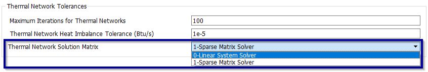
Sparse Matrix Solver has been introduced for Thermal Network solution. This will speed up the solution time for thermal network models. ~35% reduction in solution time is achieved in comparison to current Linear solver. With the new Sparse Matrix Solver, Flow Simulator solver capability is enhanced to solve ~300000 thermal nodes in the model. The Sparse Matrix solver options is available under Solution Panel → Solvers Convergence → Thermal Network tolerances → Thermal Network Solution Matrix
-
Pressure and Temperature Limits during the solution are added to avoid divergence of certain models & Fluid Temperature Damping is introduced.
-
Controller → Friction multiplier for the Tube & Incompressible Tube has been added for Gauge & Manipulation.
-
XML results have been added for all the missing elements
-
End of run summary for errors, warnings and cautions are now more detailed
Resolved Issues - 20.1 Production Release
Graphical User Interface (GUI) Bug Fixes
- Issues with Controller Borrow from Spec’s has been addressed
- Issues with Chamber Fluid Options display error has been resolved
- Issues related to Cavity Autofill options, Active & Inactive of flows are addressed
- IGES scaling crash has been resolved
- PlateFin heat exchanger material options are not retained – resolved
- PlateFin Heat exchanger Property editor updates on No. Of Passages input – resolved
- Probabilistic Create Error – when no of results files didn’t match no of runs. – resolved
- Results Viewer loading taking too much time – resolved
- Solid Material Menu - Edit Button doesn't work as expected – resolved
- Data Based Pump Head and Flow Tables Flipped – resolved
- Results Table Temperature Unit for Thermal Network models– resolved
- No Row for Tank Port Information when attached to junctions & Heat exchangers – resolved
- Vermes Seal property editor doesn’t retain rotor/stator flag Display error – Resolved
- Apply button doesn't work in Emulsion Mixture – Resolved
- Failed to read result data after running completes – Resolved
- Flow Simulator Solve button is inactive after Transient run Completes – Resolved
- After a transient run converges, results files are not loaded to results viewer (Run Model & Result) – Resolved
- Temperature values are not converted correctly for Display Options in GUI – Resolved
- Result file not found message after loading results - Resolved
- Transformed iges shape should be saved to iges file (CAD) – Resolved
- After user drag element to a vertex, vertex name should disappear (CAD) – Resolved
- User must be able to use iges vertices for measurements even if some geometrical transformations were done on iges loaded in the background (CAD) – Resolved
- Transient Run Control Parameters Button is disabled for transient runs (Run Panel) – Resolved
- Allow Absolute roughness to 6 digit and scientific e-notation in Face Recognition setting - Resolved
- Thermal Network → “ASSOC_SIDE” field is not updated correctly. – Resolved
- Thermal Network → ”Extract Area from element” checkbox is not retained on reloading the .flo files – Resolved
- Thermal Network → Radiator → “Simple Radiation” option → View factor LR field should not appear – Resolved
- Thermal Network → When a convector is associated with an element and then disassociated, the tubes heat transfer settings remain same. Only reopening the model enables the heat transfer settings – Resolved
- Thermal Network → When a fixed htc value changed to a relation and then again fixed htc set, the GUI does not recognize the specified htc value. Takes it as zero – Resolved
- Incompressible Tube & Advanced Orifice
- Friction → Specified Roughness → ”Roughness” text field shouldn’t appear - Resolved
- Friction → Specified Roughness → ”Roughness” define table is not correct, it should have stations, not segments -Resolved
- Above two points are applicable same for “Specified Friction Coefficient” & “Specified Friction Mult” -Resolved
- For Tube Element → Inlet k (under momentum loss) default value should be zero - Resolved
- For Tube Element → “Wall Sink Temperature” is not getting disappeared, even when we switch heat transfer options – Resolved
- “Additional Analysis Control” dialogue box is not scalable. The text fields names are truncated - Resolved
- IGES translation/rotation/Measure → I am selecting IGES vertices (IGES is translated and rotated), it is selecting, but the final distance arrow on the original location of IGES – Resolved
Solver Bug Fixes
- Fix convergence problem for open tank and steady state analysis.
- Vortex element temperature reference frame bug fixed. Fixed problem for vortex chambers with a fixed temperature (probably coming from a thermal model) used as vortex element swirl chambers. Problem occurred if temperature within the vortex element changes frame from relative to absolute.
- Fan & Compressor Module → Delta PS scale factor (Affinity Laws) is added in checking the table limit for interpolation warning & Volumetric Flow Calculation
- Multicase → Added options to add xml output and .prop files for all cases during a Multicase run
- Limited CD of CDCOMP element between 0.01 and 1
- Thermal Network → HTC of a convector was not updated when a controller element changes it, now HTC of a convector can be changed by a controller.
- Thermal Network → HTC correlations were not working when a convector is attached to a chamber. This is fixed, and now all correlations work
- CDCOMP_FLOINHANCE → inclination angle limited to 30 instead of 35 for Correction for pumping due to orifice inclination.
- Vermes Seal → Issues with Critical Mass Flow Rate under chocking condition. The problem involved a part of the vermes seal loss calculation called “BETA”. The tests that were used to come up with the BETA equation were all subsonic. Since the BETA equation uses the overall pressure ratio it was decreasing after the pressure ratio exceeded the choking pressure ratio. We have added a maximum limit for the pressure ratio used in the BETA equation. The limit is the choking pressure ratio that is based on the number of teeth.
- Error Traps have been updated for Bend element's bend radius, bend angle, aspect ratio and width
- Error Trap for ValvePos vs CD Table has added
- Vortex element radii of 0 checks has been enabled