Highlighting Specific Mesh Elements
The mesh highlight tool allows you to view areas of the mesh where specific model settings are applied.
On the 3D View contextual tabs set, on the
Mesh tab, in the Tools
group, click the  Highlight icon. From the drop-down list select one of the following:
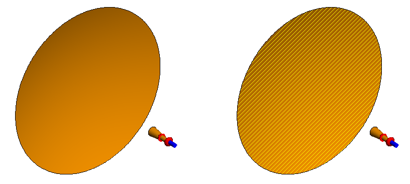
Figure 1. On the left, a 3D view of a horn and a reflector with no highlighting
applied. To the right, the reflector is highlighted in yellow to
indicate that PO solution method is
applied to the face.
-
 None
None- No mesh elements are highlighted.
-
 Lossy
metal
Lossy
metal- Highlight mesh elements (faces, wires) with a metallic medium and thickness applied to it.
-
 Coating
- Highlight mesh elements (faces, wires, edges) with a coating (layered dielectric) applied to it.
-
 CFIE / MFIE
- Highlight mesh elements (faces) with either a combined field integral equation (CFIE) or magnetic field integral equation (MFIE) applied to it.
-
 EFIE
EFIE- Highlight mesh elements (faces) with the electric field integral equation (EFIE) applied to it.
-
 Impedance
sheet
Impedance
sheet- Highlight mesh elements (wires, faces) with an impedance sheet applied to it.
-
 Surface
impedance approximation
Surface
impedance approximation- Highlight faces that bound a region set to the dielectric surface impedance approximation.
-
 Physical
Optics
Physical
Optics- Highlight mesh elements (faces) with the physical optics (PO) solution method applied to it.
-
 Physical
Optics (Fock regions)
Physical
Optics (Fock regions)- Highlight mesh elements (faces) with the physical optics (PO) solution method applied to a Fock region.
-
 Ray
Launching GO
Ray
Launching GO- Highlight mesh elements (faces) with the ray launching geometrical optics (RL-GO) solution method applied to it.
-
 Uniform
Theory of Diffraction
Uniform
Theory of Diffraction- Highlight mesh elements (faces) with the uniform theory of diffraction (UTD) solution method applied to it.
-
 Faceted
Uniform Theory of Diffraction
Faceted
Uniform Theory of Diffraction- Highlight mesh elements (faces) with the faceted uniform theory of diffraction (faceted UTD) solution method applied to it.
-
 FEM
FEM- Highlight mesh elements (regions) with the finite element method (FEM) solution method applied to it.
-
 VEP
VEP- Highlight mesh elements (regions) with the volume equivalence principle (VEP) solution method applied to it.
-
 Windscreen
solution elements
Windscreen
solution elements- Highlight mesh elements (faces, wires) that are specified as windscreen solution elements (windscreen antenna elements).
-
 Aperture
- Highlight a slot or aperture in an infinite plane with the planar Green's function aperture applied to it.
-
 Numerical
Green's Function
Numerical
Green's Function- Highlight mesh elements defined as the static part using the numerical Green's function.