Creating the Model
Create the model in CADFEKO. Define any ports and sources required for the model. Specify the operating frequency or frequency range for the model.
-
Import the Parasolid geometry of the car from the file
car_geometry.x_b
Note: The model is included in the Feko installation.
-
Rename the three imported parts as follows:
- The structure for the car: car_body.
- The structure for the antenna: antenna.
- The structure for the windscreen: windscreen.
-
Union car_body and antenna.
Note: The windscreen curvature reference is not part of the union as it is not required to be electrically connected to the model.
- Add a wire port to the start of the line.
- Add a voltage source to the port. (1 V, 0°, 50 Ω).
-
Create a dielectric medium (glass).
- Relative permittivity: 7
- Dielectric loss tangent: 0.03
- Label: glass
-
Create a dielectric medium (PVB foil).
- Relative permittivity: 3
- Dielectric loss tangent: 0.05
- Label: pvb_foil
-
Create a layered dielectric (2D).
-
Create a windscreen medium.
-
Specify the windscreen curvature reference.
A windscreen curvature reference is displayed semi-transparent in the colour of the windscreen definition.
-
Specify the windscreen antenna (wires).
Figure 1. 3D view showing the selected windscreen antenna. 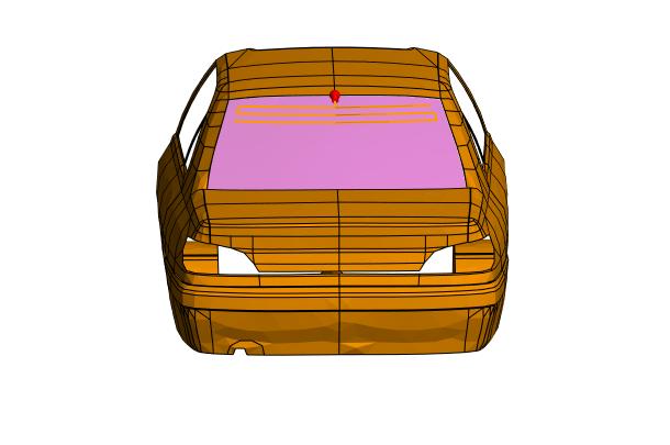
- Set the continuous frequency range from 90 MHz to 110 MHz.