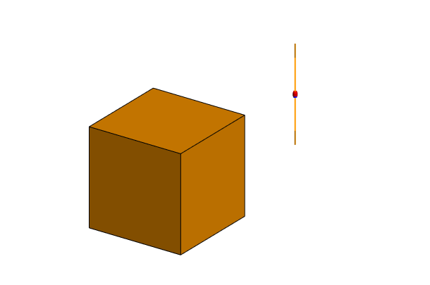
Dipole in Front of a Cube
Calculate the radiation pattern for a half-wavelength dipole in front of a cuboid. View the effect of the cuboid on the radiation pattern.
The far field results are compared for the following cuboid configurations:
- Perfect electric conductor (PEC) cuboid
- Lossy metallic cuboid
- Dielectric cuboid
Tip: Each model uses its predecessor as a starting
point. Create the models in their presentation order. Save each model to a new
location to keep them.