Creating the Model
Create the model in CADFEKO. Define any ports and sources required for the model. Specify the operating frequency or frequency range for the model.
-
Define the following variables:
- freq = 46.29e6 (The operating frequency.)
- lambda = c0/freq (The wavelength in free space.)
- tau = 0.93 (The growth factor.)
- sigma0 = 0.7 (Spacing)
- sigmaN = sigma(N-1)/tau, where N is iterated from 1 to 11 with an increment of 1.
- d0 = 0 (Position of the first element.)
- dN = d(N-1) – sigmaN, where N is iterated from 1 to 11 with an increment of 1.
- len0 = 2 (Length of the first element.)
- lenN = len(N-1)/tau, where N is iterated from 1 to 11 with an increment of 1.
- rad0 = 0.00667 (Radius of the first element.)
- radN = rad(N-1)/tau, where N is iterated from 1 to 11 with an increment of 1.
- Zline = 50 (Transmission line impedance.)
- Zload = 50 (Shunt load resistance.)
-
Create twelve dipoles.
- Add a voltage source to the first dipole1 (1 V, 0°, 50 Ω).
-
Create eleven transmission lines to connect the dipoles.
-
Connect TransmissionLineN between
Port(N-1) and Port(N) in the
Network schematic view, where N is
iterated from 1 to 11 with an increment of 1.
Figure 1. The network schematic view showing the connected transmission lines, general networks and ports. 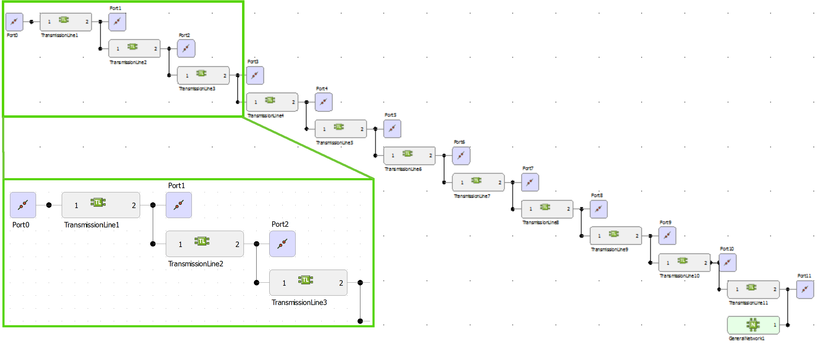
-
Define a shunt load using a general network.
- Specify the one-port Y-matrix manually.
- Y11 = 1/Zload
-
View transmission line 11 in the Network schematic
view.
- Connect the general network to port 11.
- Set the continuous frequency range from 35 MHz to 60 MHz.
1 This is Line0
with WirePort0.