END RING
Overview
 |
|
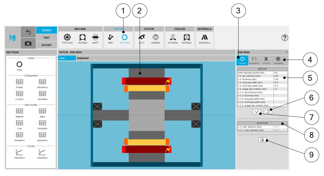
| END RING – DESIGN - design area | |
| 1 | Selection of the ROTOR subset: END RING panel (Click on the icon END RING) |
| 2 | Visualization of the axial view of the machine |
| 3 |
DESIGN tab indicates the tools to define the end ring topology and parameter values Note: By default, DESIGN tab is selected
|
| 4 |
A section scrolling bar allows choosing the section in which user inputs are defined. Scrolling selection bar where Design, Impedance, X-Factor and operating conditions sections can be selected. |
| 5 |
Definition of the end ring dimensions on both sides of the machine. Definition of each end ring geometrical input, with the corresponding arrow on the axial view of the machine |
| 6 | Buttons to restore default input values. See “Part Factory” application for more information. |
| 6 | Buttons to apply inputs (Pressing the “enter key” twice applies inputs too). |
| 7 | End ring outputs (read only) |
| 8 | Icon to export end ring data into *.txt or *.xls files. |
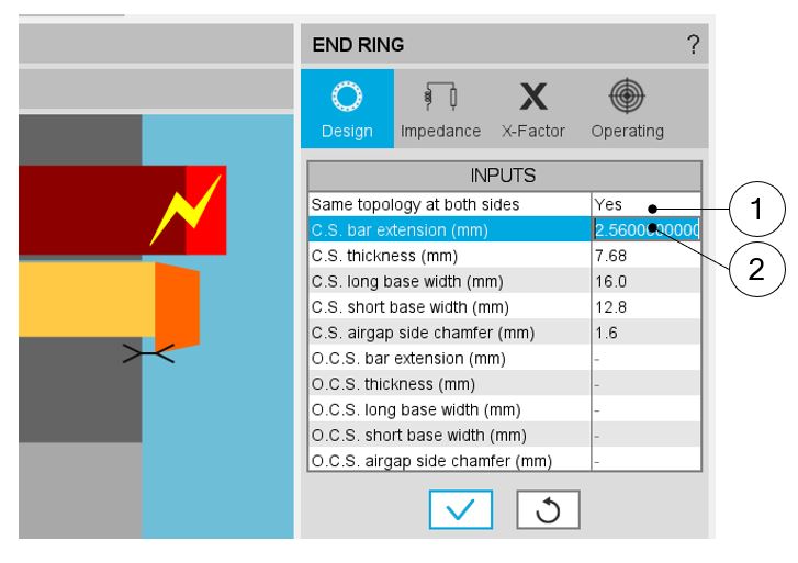
End ring – Design – Inputs / Outputs
 |
|
| END RING - DESIGN – design area | |
| 1 | Selector to choose same end ring topologies on both sides |
| 2 | Definition of each end ring geometrical input, with the corresponding arrow on the axial view of the machine |
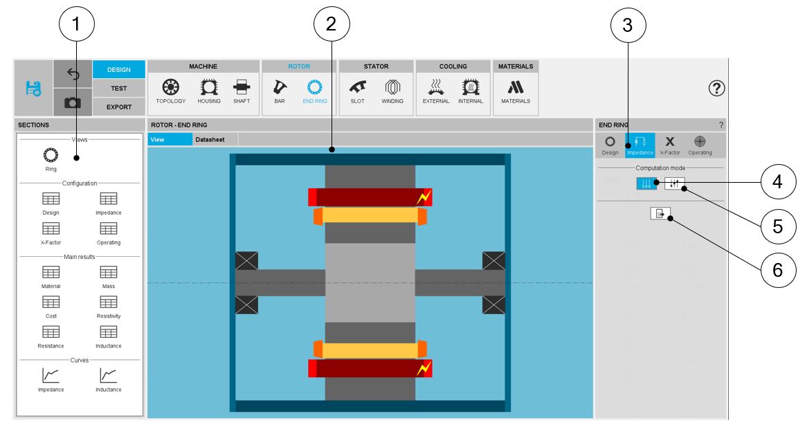
End ring - Inter bar Impedance
The aim of this section is to compute the inter bar impedance of the squirrel cage.
 |
|
| END RING - IMPEDANCE area | |
| 1 | Shortcut panels to navigate in the impedance results |
| 2 | Main window for results |
| 3 | Section dedicated to inter bar impedance definition |
| 4 | Automatic computation mode |
| 5 | Constant computation mode |
| 6 | Icon to export end ring impedance data into *.txt or *.xls files. |