WCDMA (Dynamic Simulations)
View the settings for code division multiple access.
Air Interface Parameters
All parameters related to a selected air interface can be specified on the Air Interface tab of the Edit Project Parameter dialog. For code division multiple access, the following settings are available.
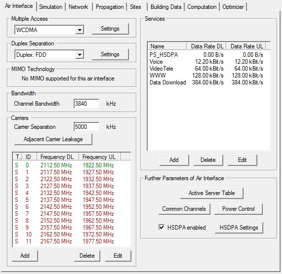
- Multiple Access Settings
- Clicking on the Settings button will open a dialog, where the chip rate of the carrier can be defined.
- Duplex Separation
- Separation of uplink and downlink can be chosen to be either in frequency (frequency division duplex) or in time (time division duplex). Further settings related to the duplex separation can be specified by clicking on the Settings button.
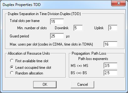
In the case of TDD mode, some further parameters are required. The dialog below shows a possible UTRAN TDD parameterization. A frame is subdivided into a certain number of slots. These slots are assigned to the uplink and the downlink direction according to the traffic request. Therefore it is possible to utilize the spectrum more efficiently in case of asymmetric traffic demand compared to the FDD case with equal uplink and downlink bandwidth. To reduce interference, sectors of a single site use the same time slots for uplink and downlink transmission. Therefore the traffic demand is analyzed per site and the time slots are assigned to uplink and downlink according to the respective traffic demand. The minimum number of time slots that are used for uplink and downlink can be specified. To ease synchronisation and reduce interference the TDD mode provides a guard period. The guard interval can be specified in µs. Within this interval perfect synchronization is assumed. The guard period limits the cell range (signal delay to the cell edge must be smaller than half of the guard period). In the simulation all mobiles with signal delays larger than half the guard period will be blocked, thus 25µs corresponds to a maximum cell range of 3.75km.
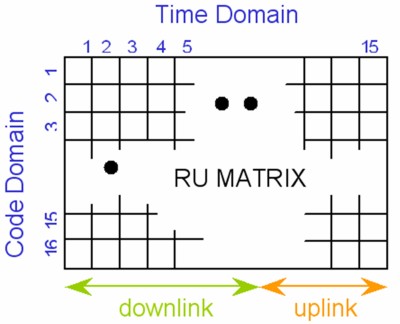
The number of Resource Units (RU) that are available in a TDD time slot can be specified. In case of a CDMA network, this corresponds to the number of available codes. In UTRAN TDD a maximum spreading factor of 16 specified leading to 16 RU per time slot. Services with higher bandwidth demand will be served with several SF16 codes in parallel, or with the reduced spreading factor. This can be mapped to the assignment of several RU per time slot to individual mobiles. That means that the TDD radio resources are consist of two-dimensional matrix with the granularity of one RU. The dimensions are the number of time slots and the number of codes (maximum spreading factor). The number of switching points is reduced to limit the interference. One block of downlink slots is generated at the beginning of the frame, the remaining time slots at the end of the frame are used for the uplink.
- First available time slot: For each mobile, the first time slots of the respective downlink and uplink block are checked if they can be used to set up a new connection.
- Least occupied time slot: The time slots with less occupied RU are tested first to set up a connection.
- Random allocation: available RU are searched in randomly among the respective downlink and uplink time slots.
In TDD networks mobile-to-mobile (MS-MS) interference and cell-to-cell (BS-BS) interference arise. These sources of interference are considered during simulation assuming a LOS connection with the respective antenna pattern. The propagation coefficient can be specified separately for the MS-MS and BS-BS interference. For BS-BS interference the coefficient may be quite low in the case of ‘over-rooftop’ mounted antennas, for example, 2.5. In the case of MS-MS interference, the propagation coefficient may be somewhat higher in urban scenarios, resulting in higher MS-MS attenuation due to the NLOS situation.
- MIMO technology
- MIMO technology is not supported for this air interface.
- Channel Bandwidth
- The available bandwidth of the channel. This value is used to calculate thermal noise impact.
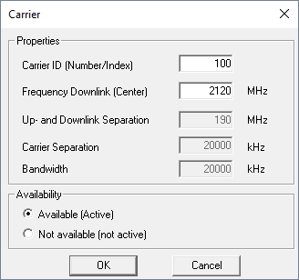
- Carrier Separation
- Frequency separation of two adjacent carriers. This value is used for the determination of adjacent or co-channel interference.
- Adjacent Carrier Leakage
- These parameters model the RF filter characteristic in terms of carrier separation. The attenuation of the neighbor carriers can be defined in discrete steps for the direct neighbor carrier (adjacent), the next carrier (alternate), and for any further carriers.
- Modulation and Coding Schemes
-
To distinguish between the different services a well-defined Name for example speech, low-data can be attributed. Using the dialog, Timing in Simulations, you can specify the Setup and Drop timers for the actual service. These values define the time a new MS waits to get a connection or an established MS holds a connection in case of insufficient signal quality, respectively. The parameter Data Rate defines the bit rate of the corresponding service. By the activity factors for uplink and downlink, the effective data rate can be reduced if the transmission channel is not required continuously.
A typical example is the speech service with activity factors of about 60% each (50% + signaling). Additionally, asymmetric data services can be considered by utilizing these values. The Eb/N0 values define the ratio between signal power density to noise- and interference power density, which is required at the receiver after despreading for a specific bit error rate. These values depend on the receiver implementation and can be taken from link level simulations. In CDMA simulations the effective data rate is considered in the computation of the processing gain. Consequently, if we specify the net-bit rate, the Eb/N0 values taken from link level simulations have to refer to the net bit rate also. Physical layer overhead (for example coding rate) is therefore taken into account by the link level simulations.
The maximum possible transmitting power of the MS can be limited for each service individually by specifying the maximum output power of the amplifier. For mobile data and speech services in W-CDMA simulations usually, the specified power classes 3 and 4 (from the 3GPP standard) with power limits of 24dBm and 21dBm, respectively are taken into account.Note: During simulation, the uplink power limit is reduced by the Fast Fading Margin.Therefore the maximum power that can be found in the result files can be less than the specified maximum amplifier power, even at the cell borders. Additionally, for each service the maximum transmitting power in the downlink can be limited. This can be helpful especially for the evaluation of asymmetric data services.Note: This is the power that can be used per single downlink connection. The overall power amplifier parameters (including power limit) have to be set via the Sites/transmitters dialog.
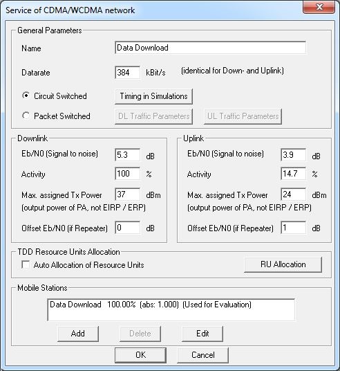
The allocation of resource units for a mobile depending on the service specification (bit rate) can be done either automatically or manually for each service in TDD mode. Press the RU Allocation button and set the required RU for uplink and downlink in time domain and code domain. (In TDMA access scheme the code domain corresponds to the respective time slots).
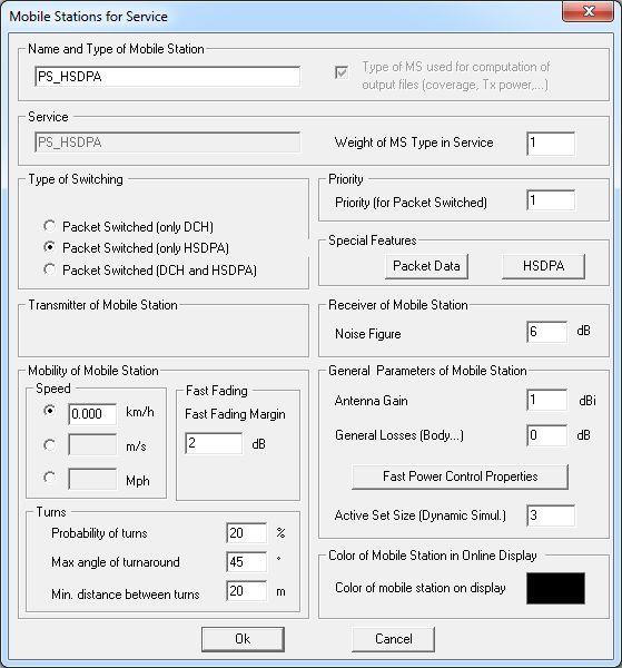
- Mobile Types
- For each service at least one type of mobile stations (mobile type) has to be
defined to specify the noise figure, antenna gain, losses, fast fading margin, and
mobility parameters. The parameter, Noise Figure, defines
the additional noise generated due to the receiver within the mobile station. The
values of Antenna Gain and General
Losses refer to the gain of the transmitting antenna (in dBi), or
the additional losses between the antenna and the power amplifier, respectively.
The parameter, Fast Fading Margin, represents the
difference (in dB) between the maximum possible transmitting power and the maximum
allowed transmitting power. To ensure the fast power control to compensate for the
deep fades of the radio channel, this specific headroom is required. Appropriate
values for this headroom have to be determined via link level simulations and will
depend on the mobile speed.
The mobility characteristic of the mobile type is determined by its speed, a minimum distance the mobile moves on straight lines, the probability for a turn after this distance and a maximum turn angle. The actual turn angle is statistically distributed between +/- maximum angle. If the traffic settings are based on the mobile location (depending on the clutter data, for example,
Hot-Spot
-scenarios or outdoor / indoor scenarios) a mobile will not leave its traffic class. That means for example that mobiles will not penetrate buildings if the building has a different traffic class. Instead, they are reflected. The same happens at the border of the simulation area. The traffic generator setting can be reached by clicking because the traffic settings can be individual or common for all services.Through a sub-dialog, the parameters of the actual MS class related to the power control can be chosen: the power control step size (for example, 1 dB in UMTS) and the SNIR margin. The SNIR margin specifies the value by which the SNIR target can be missed and the signal quality is still considered as sufficient. This is required as the actual measured SNIR will oscillate around the target SNIR (due to the closed loop power control).
If there is more than one type of mobiles per service, the number of mobiles generated of each type can be controlled by a weight factor giving the relative proportion for the different MS types within this service. One of the mobile types has to be selected to be used for the coverage tests for this service (and for the full-area-measurements).
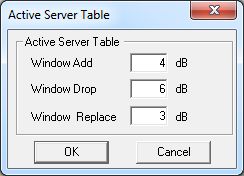
- Active Server Table
- The active set of a mobile station is the list of sectors to which a link is
established. The active set can be modified from slot to slot. There are three
operations defined on the Active Set (AS):
- Add a Link to the AS (Window Add)
- Drop a Link from the AS (Window Drop)
- Replace a Link within the AS by a better Link (Window Replace)
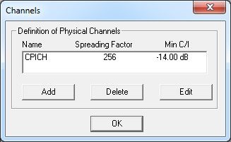
- Common Channels
- Different common channels (CCH) can be defined by pressing the respective buttons
(Add /
Delete/Edit). For each CCH the
required C/I has to be specified. Note: The channel quality C/I is measured before despreading (in contrast to Eb/N0 in the definition of the services).It is common practice to specify the CCH by their required C/I. During the simulation, ProMan assures that all defined CCH are received by the mobile station with sufficient signal quality. Otherwise the call gets blocked or dropped. The CCH transmission power can be defined through the TRX settings for all sectors in common or every sector individually. These transmission powers - together with one CCH transmission power value for CCH not explicitly defined - contribute to the interference.
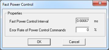
- Power Control
- The Power Control button opens a dialog that enables you
to set some general transmit power control (TPC) related parameters. First, the
interval of the closed loop power control has to be specified. This interval
determines the rate with which the power control feedback information (
power up
orpower down
) is sent from the receiver to the transmitter. In case of UMTS, this corresponds to the slot length, thus 0.667ms. Furthermore, a TPC error rate can be defined, which introduces the probability for corrupted TPC feedback commands. A typical value for this error rate is 4%.
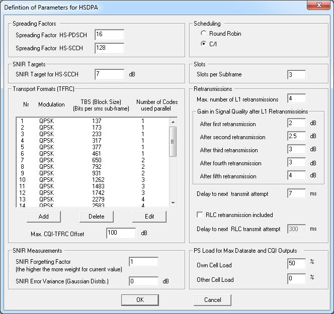
- HSPDA Settings
- If the HSDPA option is enabled, the corresponding settings can be specified on the following dialog.
Output Options
- General Results
- Best Server (Cell Assignment)
- Maximum achievable Bit Rate
- EMC Analysis
- Individual Results for each Service
- Minimum Required Transmission Power
- Further CDMA related Results for each Service
- Coverage Probability
- Soft/Softer Handover Areas
- SNIR
- Channel Quality Indicator (only for HSDPA
- Further Results for Dynamic Simulations
- Statistics and Delays for PS Services
- Locations of Mobile Stations
- Detailed MS Information