FDMA (Downlink and Uplink)
Air Interface Parameters
For frequency division multiple access in downlink and uplink the following settings are available:
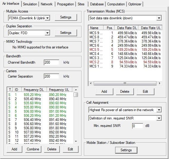
- Multiple Access Settings
- Clicking the Settings button will open a dialog, where the
power backoff used for cell assignment can be specified. This back off is defined
with respect to the maximum available transmit power of the corresponding carrier.
The resulting percentage of the total transmit power used for the pilot channel
and the data channels, respectively depends on the chosen power back off and is
shown in the dialog as well.Note: The Tx power back off should exceed 0 dB for FDMA systems. For a power back off of 0 dB, the total transmit power is used for the pilot channel and no power is left for the data channels.

- Duplex Separation
- Separation of uplink and downlink can be chosen to be either in frequency (frequency division duplex) or in time (time division duplex). Further settings related to the duplex separation can be specified by clicking on the Settings button.
- MIMO Technology
- MIMO is not supported for this air interface.
- Channel Bandwidth
- Available bandwidth of the channel. This value is used to calculate thermal noise impact.
- Carrier Separation
- Frequency separation of two adjacent carriers. This value is used for determination of adjacent or co-channel interference.
Output Options
- General Results
- Best Server (Cell Assignment)
- Maximum achievable Throughput
- This results describes the overall throughput which is possible considering the defined network with various transmission modes and possibly multiple carriers.
- EMC Analysis
- Individual Results for each Modulation and Coding Scheme
- Minimum Required Transmitter Power
- Maximum achievable Received Signal Strength
- Reception Probability (including Fast Fading)
- The Reception Probability (including Fast Fading) is computed for each transmission mode in the network-planning results by assuming a Rayleigh distribution of the signal levels due to fast fading. Based on the difference between the computed mean Signal-to-Noise-and-Interference Ratio (SNIR) and the required SNIR for the transmission mode, the reception probability is computed and reported.
- SNIR (Maximum achievable SNIR)
- Maximum Number of Parallel Streams at Pixel
- This result describes how many streams can be supported in parallel at the given location (with respect to the defined transmission mode and the overall number of available time slots).
- Throughput at Pixel in Transmission Mode
- This result describes the maximum throughput at the given location evaluating the data rate of the defined transmission mode and the maximum number of parallel streams.
- Results Related to the Cell Assignment
- Serving Carrier: Received Power (Cell Assignment)
- Serving Carrier: SNIR (Cell Assignment)
- Number of Carriers Received
- Number of TRX Received
- Number of Sites Received
- Neighbor Cell List
- Analysis of the Serving Carrier
- Serving Carrier: Received Signal, Noise + Interference
- Serving Carrier: Received Noise + Interference