CDMA / WCDMA / HSPA
Air Interface Parameters
All parameters related with a selected air interface can be specified on the Air Interface tab of the Edit Project Parameter dialog. For code division multiple access, the following settings are available:
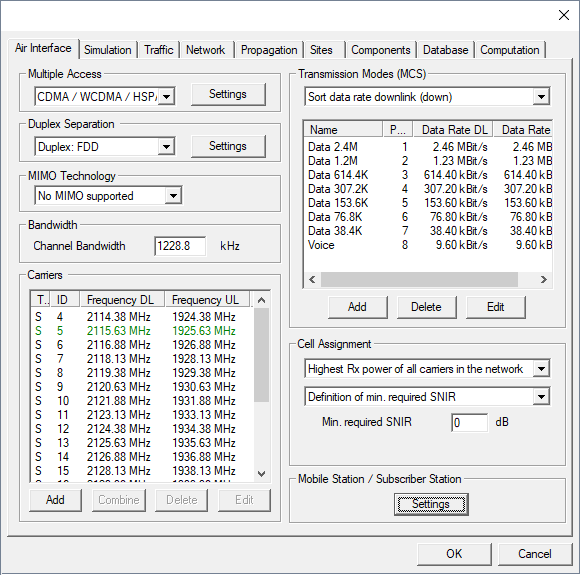
- Multiple Access Settings
- Click on the Settings button to open a dialog, where the multiple access parameters can be defined.
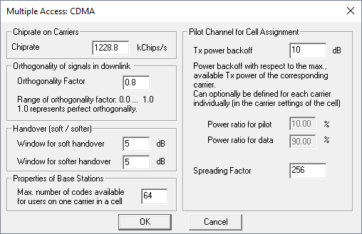
- Orthogonality of Signals in Downlink
- Physically the orthogonality depends on the multipath channel conditions and the receiver implementation. Pure line-of-sight (LOS) profiles lead to nearly perfect orthogonality (DOF approximate 1), while non-line-of-Sight (NLOS) profiles have reduced orthogonality depending on the degree of multipath propagation (for example DOF = 0.4 … 0.9). It is common practice in CDMA system simulations to use an average DOF for the complete simulation, thus for each downlink connection the same constant DOF is used.
- Handover (soft/softer)
- The handover type in CDMA is related to the number of cells which are received within a certain window. The window sizes for soft and softer handover can be defined in the corresponding fields. If only one cell is received, no handover is possible at all. In case two cells are received within the defined handover window, soft handover is possible. If two cells (sectors) from one site are received within the defined window, softer handover is possible. If two cells (sectors) from one site and another cell from another site are received within the defined windows, both soft and softer handover is possible.
- Properties of Base Stations
-
To achieve higher data rates multiple codes can be used in parallel within a single transmission mode (for example in UMTS HSPA). This maximum number of codes, which are available for users operating on the same carrier within a cell, can be defined.
Note: The throughput results depend on the maximum number of available codes as the feasible data rate for one user is multiplied with the number of possible streams. Additionally, the number of parallel used codes defined on transmission mode level should be below this maximum number. - Pilot Channel for Cell Assignment
-
The Tx power backoff used for the cell assignment can be specified in dB and is defined with respect to the maximum available transmit power of the corresponding carrier. The percentage of the total transmit power used for the pilot channel and the data channels respectively depend on the chosen power backoff and are shown in the dialog as well.
Note: The Tx power backoff should exceed 0 dB for CDMA systems. For a power backoff of 0 dB, the total transmit power is used for the pilot channel, thus no power is left for the data channels.
- Duplex Separation
- Separation of uplink and downlink can be chosen to be either in frequency (frequency division duplex) or in time (time division duplex). Further settings related to the duplex separation can be specified by clicking on the Settings button.
- MIMO Technology
- MIMO technology can be either disabled or enabled using two or four parallel streams.
- Channel Bandwidth
- Available bandwidth of the channel. This value is used to calculate thermal noise impact.
- Carrier Separation
- Frequency separation of two adjacent carriers. This value is used for determination of adjacent or co-channel interference.
Output Options
- General Results
- Best Server (Cell Assignment)
- Maximum Achievable Throughput
- This result describes the overall throughput which is possible considering the defined network with various transmission modes and possibly multiple carriers. Additionally, the maximum achievable data rate is predicted as well.
- EMC Analysis
- Individual Results for each Modulation and Coding Scheme
- Minimum Required Transmitter Power
- Maximum achievable Received Signal Strength
- Reception Probability (including Fast Fading)
- The Reception Probability (including Fast Fading) is computed for each transmission mode in the network-planning results by assuming a Rayleigh distribution of the signal levels due to fast fading. Based on the difference between the computed mean Signal-to-Noise-and-Interference Ratio (SNIR) and the required SNIR for the transmission mode, the reception probability is computed and reported.
- Maximum achievable Ec
- In UMTS the RSCP stands for Received Signal Code Power – the energy per
chip in CPICH. This means the RSCP corresponds to the
Received Ec
in ProMan (energy per chip).
- In UMTS the RSCP stands for Received Signal Code Power – the energy per
chip in CPICH. This means the RSCP corresponds to the
- Maximum achievable Eb
- The
Received Eb
(energy per bit) is the sum of the Ec and the spreading gain.
- The
- Maximum achievable Ec/(N0+I0)
- The Ec/(I0 + N0) describes the situation before despreading. Accordingly I0 includes the full interference power density of the own cell (independent of the defined orthogonality factor) as well as the interference power density of the neighboring cells and the noise power density. Ec is the energy per chip.
- Maximum achievable Eb/N0
- The Eb/N0 describes the situation after despreading, which extracts by correlation the desired signal out of the interference mix. Accordingly, the Eb (energy per bit) is the sum of the Ec and the spreading gain. The interference power density of the own cell is reduced by factor (1-alpha), with alpha being the defined orthogonality factor.
- Maximum Number of Parallel Streams at Pixel
- This result describes how many streams can be supported in parallel at the given location (with respect to the defined transmission mode and the overall number of available codes).
- Throughput at Pixel in Transmission Mode
- This result describes the maximum throughput at the given location evaluating the data rate of the defined transmission mode and the maximum number of parallel streams.
- Results related to the cell assignment
- Serving Carrier: Received Power (Cell Assignment)
- Serving Carrier: Eb/N0 and Ec/Nt (Cell Assignment)
- Pilot: Total received (signal + noise + interference)
- Pilot: Interference level (noise + interference)
- Handover Regions (Soft / Softer / Hard)
- Number of Carriers Received
- Number of TRX Received
- Number of Sites Received
- Neighbor Cell List