SS-T: 5060 Structural Envelope
Tutorial Level: Intermediate
- Purpose
- SimSolid performs meshless
structural analysis that works on full featured parts and assemblies, is
tolerant of geometric imperfections, and runs in seconds to minutes. In this
tutorial, you will do the following:
- Learn how to perform structural envelope for a set of structural linear subcases.
- Model Description
- The following model file is needed for this tutorial:
- Structural_Envelope.ssp
-
Figure 1. 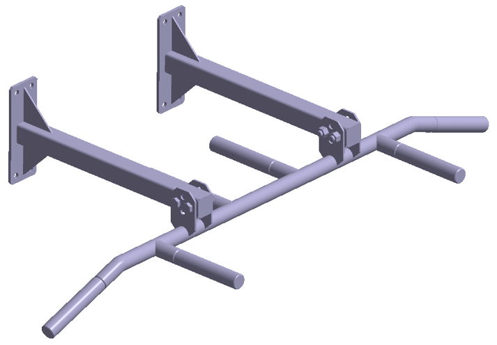
- Material is set to Steel for all parts
- Regular connections with bonded contact and fastener connections are created automatically
- Static subcases are pre-defined and solved
Open Project
- Start a new SimSolid session.
-
On the main window toolbar, click Open Project
 .
.
- In the Open project file dialog, choose Structural_Envelope.ssp
- Click OK.
Review Loads and Boundary Conditions
Review Structural Results
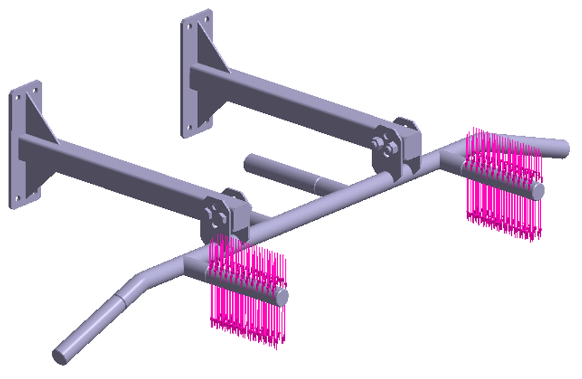
- In the Project Tree, select the Structural 1 subcase.
-
On the Analysis Workbench, select
 (Results plot) > Displacement Z.
The Legend window opens and displays the contour plot.
(Results plot) > Displacement Z.
The Legend window opens and displays the contour plot.Figure 5. 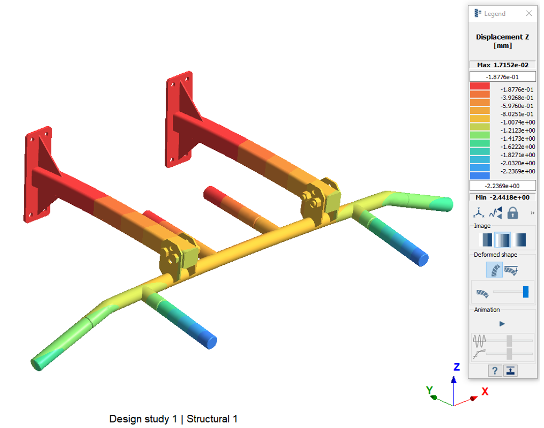
For Structural 1, the displacement is higher along the negative direction of the z-axis.
-
Repeat steps 3.1 through 3.2 to review the results for Structural 2 and
Structural 3 subcases.
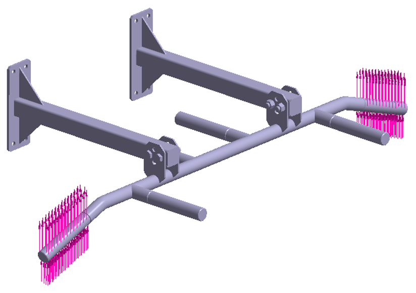
Figure 6. 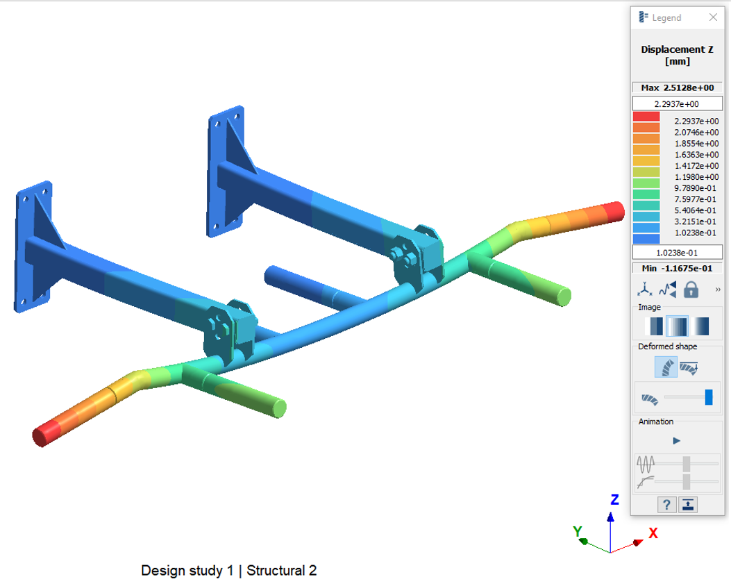
For Structural 2, the displacement is higher along the positive direction of the z-axis.
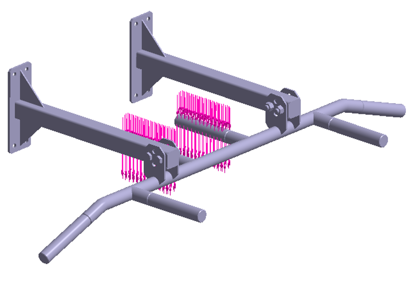
Figure 7. 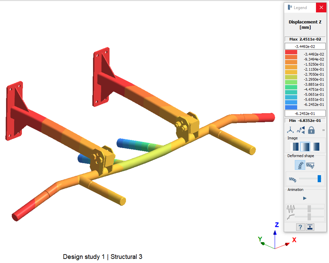
For Structural 3, the displacement is higher along the negative direction of z-axis.
Create Structural Envelope Subcase
-
On the main window toolbar, click
 (Post
study) > Structural envelope.
(Post
study) > Structural envelope.
- In the setup dialog, under Analyses available, select Structural 1.
- In the dialog, hold down Control + Shift and select Structural 3.
-
Click
 to combine
analyses.
to combine
analyses.
- For Type of envelope analysis, select Min.
-
Click Solve.
A Structural Envelope 1, Min subcase appears in the Project Tree.
-
Repeat the process from step 4.1 to step 4.4 to create Structural
Envelope 2, Max and Structural Envelope 3,
Extreme. Respectively, select Max and
Extreme as the Type of envelope
analysis, and then click Solve.
Note: Envelope minimum, maximum, and extreme finds the minimum, maximum and absolute maximum value respectively among all the selected analysis weighted by appropriate scale factors.
Review Envelope Results
- On the Project Tree, open the Analysis Workbench.
- Select Structural Envelope 1, Min from the Project Tree.
-
Click
 (Pick info).
- In the dialog, for Response type, select Displacement Z from the drop-down.
- Select the Pick point radio button.
-
In the modeling window, select a point on the model
surface as shown in Figure 8.
Figure 8. 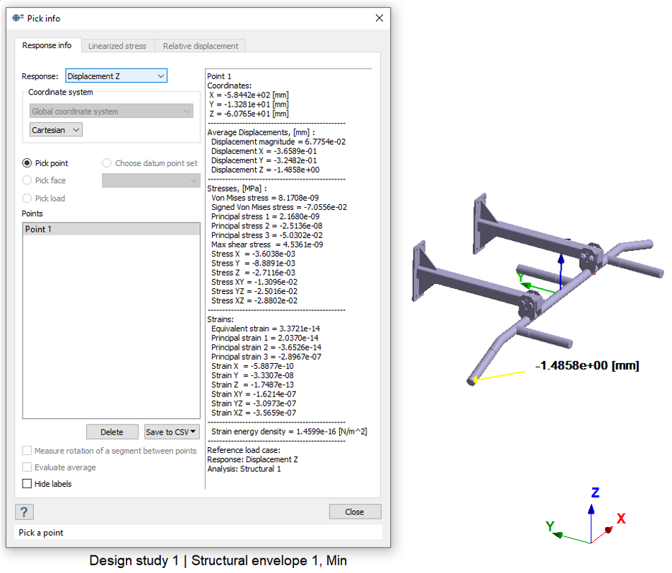
Based on the selected point, the reference load case for the minimum value among the enveloped structural subcases is shown in the right bottom side of the dialog. The figure above is from Structural 1.
-
Repeat the process from step 2 to 6 by selecting the Structural
Envelope 2, Max and Structural Envelope 3,
Extreme subcases in the Project Tree
respectively.
Figure 9. 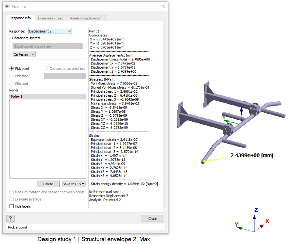
Based on the selected point, the reference load case for the maximum value among the enveloped structural subcases is shown in the right bottom side of the dialog. The figure above is from Structural 2.
Figure 10. 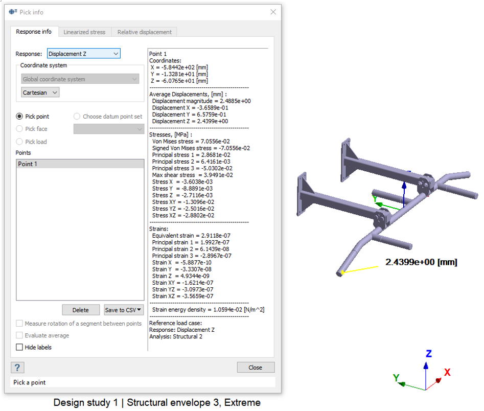
Based on the selected point, the reference load case for the absolute maximum value among the enveloped structural subcases is shown in the right bottom side of the dialog. The figure above is from Structural 2.