SS-T: 5050 Seam Welds Post-Processing
Seam weld reaction post-processing.
- Purpose
- SimSolid performs meshless structural
analysis that works on full featured parts and assemblies, is tolerant of
geometric imperfections, and runs in seconds to minutes. In this tutorial,
you will do the following:
- Learn how to post-process seam weld reactions.
- Model Description
- The following model file is needed for this tutorial:
- SeamWeld_reactions_Post-processing.ssp
-
Figure 1. 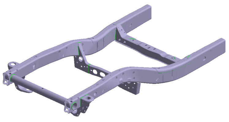
Open Project
- Start a new SimSolid session.
-
On the main window toolbar, click Open Project
 .
.
- In the Open project file dialog, choose SeamWeld_reactions_Post-processing.ssp
- Click OK.
Review Model
- Right-click on the Assembly in the Project Tree and select Info to review the model information. This includes number of parts, number of seam welds, and other key parameters.
-
Once, reviewed, close the Assembly Info dialog and expand the Structural
subcase available in the Project Tree. Review the loads
and boundary conditions created. Note that the model is solved.
Figure 2. 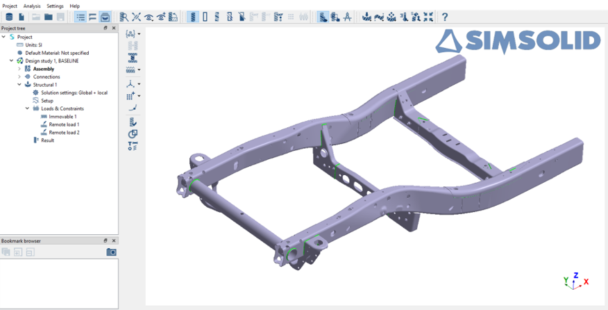
Evaluate Seam Weld Reactions for Force/Moments
- In the Project Tree, select the Structural 1 subcase.
-
On the Analysis Workbench, click
 and select
Seam weld reactions.
and select
Seam weld reactions.
- In the dialog, ensure you have the Forces/moments tab open.
-
Click Evaluate to calculate the parameters for each of
the welds for force/moments.
The corresponding values were evaluated for each of the seam welds as shown in the below image.
Figure 3. 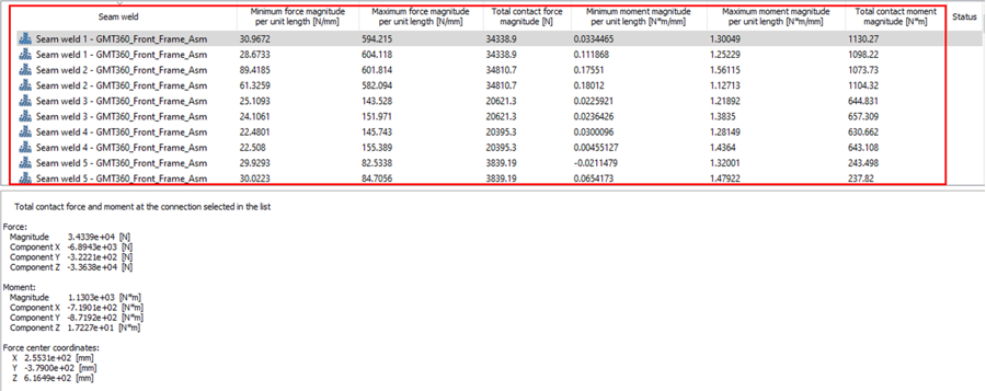
- Optional: Click the header of each parameter to sort from maximum to minimum or vice versa.
-
Select a weld from the list to view the force and moment direction in the
modeling window. To zoom in on the location of the
select weld,
 .
.
Figure 4. 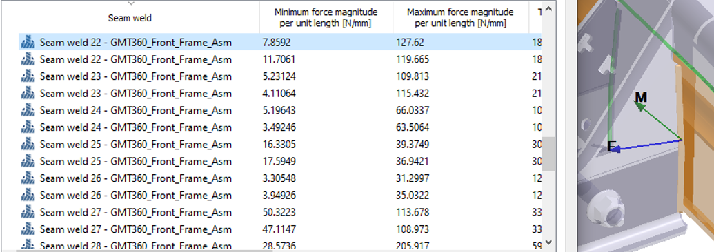
Evaluate Seam Weld Reaction for Stresses
-
In the Analysis Workbench, click and select
Seam weld reactions.
- In the dialog, select the Stresses tab.
-
In the dialog, click Evaluate to calculate the
parameters for each of the weld reaction stresses.
The corresponding values were evaluated for each of the seam welds as shown in the below image.
Figure 5. 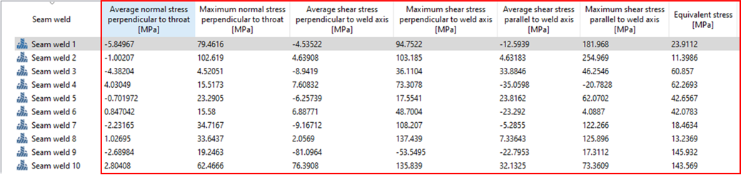
- Optional:
In the dialog, enable the Include weld section stresses,
and then set Section length to throat thickness ratio to
6.0. This evaluates the seam weld reaction for
stresses based on the ratio.
Sections are further divided for an individual seam weld section based on the Section length to throat thickness ratio input as shown in the image below.
Figure 6. 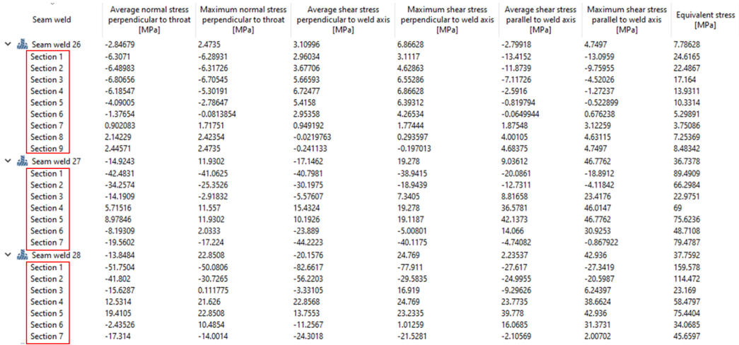
Note: Total contact forces and average stresses are displayed for each weld but seam weld resultant forces and stresses at the throat can also be evaluated per unit length. The number of data points for this evaluation is determined automatically by the length of the weld. Resultant forces and stresses per unit length can be used with seam weld design standards, specifically Eurocode 3 (EN 1993-1-8: Eurocode 3: Design of Steel Structures, Section 4.5.3). - Optional: Click the header of each parameter to sort from maximum to minimum or vice versa.
Validate Seam Weld Reactions for Force/Moments
- In the dialog, ensure you are in the Force/moments tab.
-
Enter the value for Force per unit length, and then
click Validate.
The evaluated values are validated based on the provided failure criteria and show the status for each of the welds. The welds not within the threshold limit will have a failed status (highlighted in red).
Figure 7. 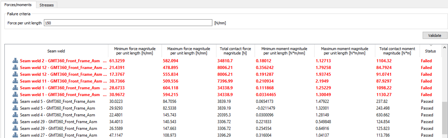
- Optional: Click the header of the status column to organize the failed and passed welds.
Validate Seam Weld Reactions for Stresses
- In the dialog, select the Stresses tab.
-
Enter the value for any of the available criteria as a combination or
individually (Normal stress, Shear stress, or Equivalent stress), and then click
Validate.
The welds are separated based on the criteria input. The welds which are not within the threshold limit show their status as failed (highlighted in red).
Figure 8. 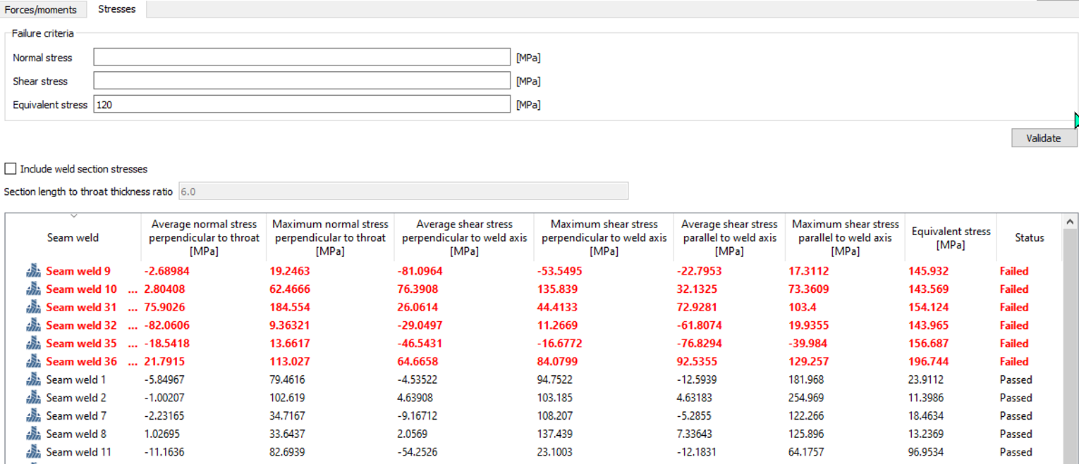
Note: If the seam welds are evaluated by including the weld section stresses, then validation is done including the sections created for all the seam welds individually as shown below.Figure 9. 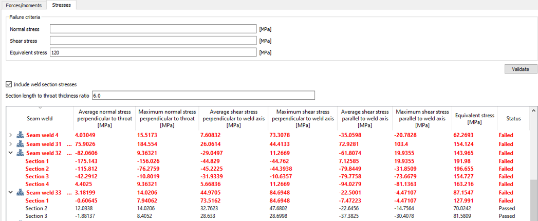
Plot Reactions versus Weld Distance [mm]
- From the seam weld list, select any weld.
- In the dialog, select a reaction type, and then click Show.
-
Click Show.
A plot along the distance of the weld versus the selected reaction type will be generated as shown below.
Figure 10. 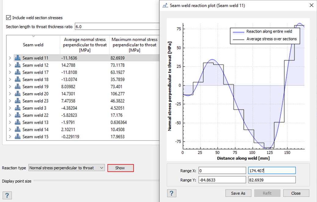
Note: The same can be some for seam weld reactions evaluated for Force/moment or Stresses. - Optional: The graph can be saved in .png, .bmp, .pdf, or .txt.
- Click Close.
- In the Seam weld reaction dialog, click Export to export to a .csv file.