Create Spot Welds
Connect two parts over a circular area on the contacting surfaces.
SimSolid allows creation of stand alone spot welds, series of spot welds on a line, or spots from a CSV file.
- In the Project Tree, open the Connections workbench
-
On the Connections workbench toolbar, click
 > Create spot welds.
- Define the Spot diameter.
-
Select one of the following tabs:
Spot Weld Type Steps Stand alone spot - Go to the Stand alone spots tab.
- Select the number of sheets.
- In the modeling window, select a point
on the part surface for the center of the spot weld.
Based on the number of sheets selected, single or multiple spot welds are found.
- Spot coordinates in the X, Y, and Z fields can be edited.
Spots on line - Go to the Spots on line tab.
- For Number of spots, use the up/down arrows to select a number.
- In the modeling window, pick points to position the spots line.
Import - Go to the Import tab.
- Select Use part names as keywords to import connected part names with only a keyword instead of the full part name.
- Click Import and browse to the desired file.
- Click Open.
-
Click OK.
Note: Welds are only found within a tolerance of the spot weld diameter. So, for a 5mm weld, the XYZ values must be within 5mm of the part surfaces.Tip: The 2T, 3T, and 4T spot welds can be visualized in different colors. Right-click on the spot welds in the Project Tree and click Show All. The 2T spot welds are highlighted in red, 3T in cyan, and 4T in pink.
Figure 1. 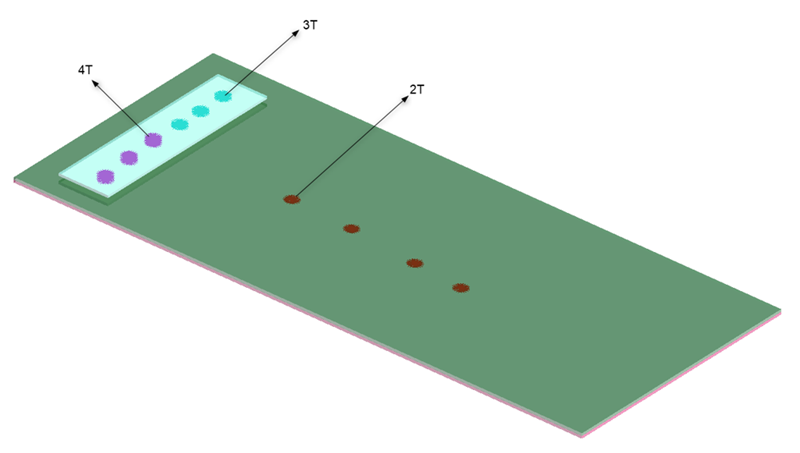
Imported Spot Weld CSV File Format
You can create a .csv file using a spreadsheet program such as Microsoft Excel or Google Sheets. The file must have a header row and one or more additional data rows (one for each spot weld). The header row can have any number of fields but only the following are read.
CSV file format fields
- “X_Pos”, “Y_Pos”, “Z_Pos” - The X, Y and Z coordinates of the spot weld location
- “Connected Part 3” (optional) - By default SimSolid creates a spot weld between the two closest parts to the XYZ value. If a 3T weld is desired, place any alphanumeric value here. This tells SimSolid to create 2 welds between the 3 closest parts.
- “Connected Part 4” (optional) - By default SimSolid creates a spot weld between the two closest parts to the XYZ value. If a 4T weld is desired, place any alphanumeric value here. This tells SimSolid to create 3 welds between the 4 closest parts.
| 1 | X_Pos | Y_Pos | Z_Pos | Connected Part 3 | Connected Part 4 |
|---|---|---|---|---|---|
| 2 | -12 | 20.7 | 0.905 | ||
| 3 | -4.6 | 14.4 | 0.6 | 3T | |
| 4 | -26 | 8.4 | 0.4 | 4T |
Format for Creating Spot Welds between Specific Parts
- “X_Pos”, “Y_Pos”, “Z_Pos” – The X, Y and Z coordinates of the spot weld location.
- "Connected part 1”, “Connected part 2” - for 2T welds – Specify the names of the parts to be connected.
- "Connected Part 3" – for 3T welds (optional) – Specify the name of the third part to be connected with spot welds.
- "Connected part 4" – for 4T welds (optional) - Specify the name of the fourth part to be connected with spot welds.
In the example below, rows 2, 3, and 4 create 4T, 3T, and 2T spot welds between the specified parts.
| 1 | X_Pos | Y_Pos | Z_Pos | Connected Part 1 | Connected Part 2 | Connected Part 3 | Connected Part 4 |
|---|---|---|---|---|---|---|---|
| 2 | -12 | 20.7 | 0.905 | Part 4 | Part 3 | Part 2 | Part 1 |
| 3 | -4.6 | 14.4 | 0.6 | Part 3 | Part 2 | Part 1 | |
| 4 | -26 | 8.4 | 0.4 | Part 2 | Part 1 |