This section contains the user guides for the following tools: Block JIG Generator, Compare GDSII, Gerber to PCB,
Make Board Paneling, Metal Mask Manager, Mounting Data Extractor, Mounting Emulator, Router-Machine JIG Generator,
Solder Quantity Calculator, Soldering Pallet, Test Point Location Generator, and Underfill.
This section contains the user guides for the following tools: BOM, CAM, Component Arrangement Plan, CP, Golden Sample,
Logic, PCB, Redmark+, and Worksheet Planner.
The output pins of power device can be connected to the same net to flow large current. This rule checks whether the
out pins of same device are connected to the same net. And check if the output pin of target device is connected to
the specified net.
This rule navigates the power and signal nets to find the voltage, then checks if the signal voltage for the input
pin is between Vil_max ~ Vih_min. It also checks that the input power voltage for the power pin does not exceed the
allowable value.
This rule checks for the connectivity of components that have polarities.
The Polarity DFE rule checks for the connectivity of capacitors or diodes that have
polarities. Polarized components, such as electrolytic capacitors and diodes, have a
characteristic of one directional current flow. The unidirectional behavior provides
variety of useful functions in electronics design. For example, power supply
filtering, AC/DC filtering, extracting modulation from radio signals, and so on.
However, reversing the current flow may result in damaging the component or causes a
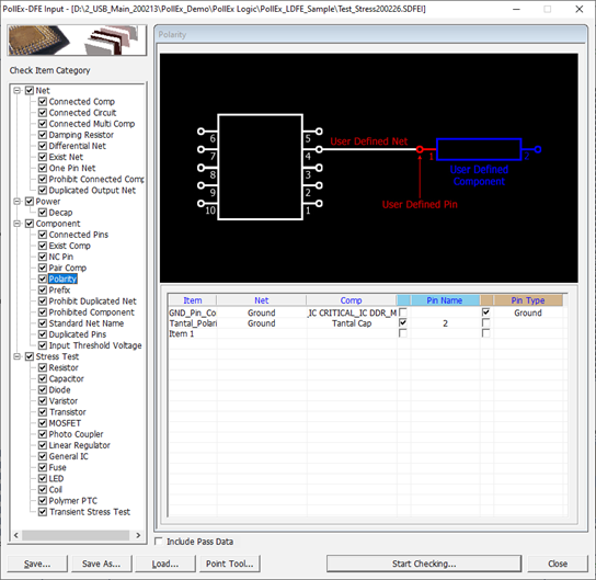
circuit malfunction. Figure 1.
Item: Input item
name.
Net: Select a
target net group that should be connected specific components.
Comp: Select a
target component group that target net should be connected.
Pin Name: Specify
the pin number string which should be connected specific net.
Pin Type: Select
the pin type which should be connected specific net.