This rule navigates the power and signal nets to find the voltage, then checks if the
signal voltage for the input pin is between Vil_max ~ Vih_min. It also checks that the input
power voltage for the power pin does not exceed the allowable value.
Item Setup
In digital logic, 1 and 0 are determined according to the magnitude of the input
voltage of the signal line. It means, if the voltage of the input signal is higher
than Vih_min, it is regarded as 1. And if the voltage of the input signal is lower
than Vil_max, it is regarded as 0. If the voltage of the input signal is between Vi
and Vh, the operation is unpredictable. Figure 1.
Item: Input item name.
Component Group: Select a target component group to be tested.
Input Pin: Select pin type of input pin to be tested.
Power Pin: Select pin type of input pin to be tested. (Pin name string or
Pin Type)
Voh:
Set the output high voltage (Voh) of driver pin. You can set this by
entering the value directly or select the property name which contain voh
value.
Vol:
Set the output low voltage (Vol) of driver pin. You can set this by entering
the value directly or select the property name which contain vol value.
Threshold: Set the input threshold of input signal and allowable value of
input power signal. Double-clicking empty field, the
Threshold dialog will be displayed. Figure 2.
Comp
Group: Select target component to be checked.
Type: Select measure type. (Value/VDD Factor)
Value: the numbers in Vil_max and Vih_Min mean voltage value.
VDD Factor: the numbers in Vil_max and Vih_Min are multiples of
VDD.
Vil_Max: The maximum voltage level that is still considered a valid "low"
signal.
Vih_Min: The minimum voltage level that is still considered a valid "high"
signal.
Test Option Setup
If the operating voltage of the IC is used at 3.3V and 5V, the 3.3V and 5V tables can
be set up respectively.
Test
Option: Set whether passive components are considered short or open when
navigating signals and power lines. Upon double-clicking the empty field,
the Test Option dialog will be displayed. Figure 3.
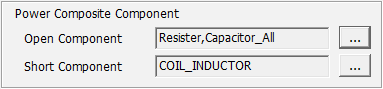
Power Composite Component Section: In this section, we declare the component to be
processed short and the component to be opened during power trace navigation. Since
Stress Test is a DC level test, the capacitor is considered as open and inductor is
considered as short. And normally the resistor is considered as open, because the
current of power net is so big that the IR-Drop can’t be ignored.
Short Component: Select the component group to be processed short during
power trace navigation.
Open
Component: Select the component group to be processed open during power
trace navigation. Figure 4.
Signal Composite Component Section: In this section, we declare the component to be
processed short and the component to be opened during signal trace navigation. Since
Stress Test is a DC level test, the capacitor is considered as open and inductor is
considered as short. And normally the resistor is considered as short, because the
current of signal net is so small that the IR-Drop can be ignored.
Short Component: Select the component group to be processed short during
signal trace navigation.
Open
Component: Select the component group to be processed open during signal
trace navigation. Figure 5.
Connector Voh/Vol Section: Normally a connector component has no property
information. In case of stress test including connector, parameter for connector pin
is needed. In this section, we can declare the voh and vol value of each connector
pins manually.
Comp
Group: Select connector component group.
Pin
Number: Enter pin number of connector component.