Differential Pair Nets 2
This item checks whether a design meets a specified shielding ratio and separation between differential pair nets.
If there is an EMI problem, one of the methods to correct the problem is to shield
with ground patterns. However, in most complicated designs, a perfect shielding is
not easy to accomplish. In that case group shielding method is allowed. In this
case, shielding grounds do not need to present between the two pair nets. In order
to shield signal nets or traces on the same layer, shielding grounds cover around
the signal traces with a certain uniform clearance. It is recommended to shield at
least 80 percent of signal net length.
- Item: Input item name.
- Diff Pair Net Group: Select Differential Pair Net Group.
- Filter: Enter a filter to choose differential pair net from selected net group.
- GND Net Group: Specify a ground net group.
- Component Keep IN/OUT: Define test region. For example, you can test inside
or outside the breakout region of CPU with different test
values.
- Component Group: Select required component group which is used for defining the test region.
- Region: Define the required test region.
- IN: DFE tests the inside of the breakout region of target component.
- OUT: DFE tests the outside of the breakout region of target component.
- Range (COC+distance): Enter the distance value to define breakout range. The COC (Component Overlap Check) plus this distance value is considered the test range.
- Target Layer: Select the required test layer.
- All Layer: Test all layers.
- Component Place Layer: Test only component placement layer.
- Different Rule Setup in Special Region: Assign additional test
region for breakout region testing.
- Extended Region from COC: Enter the distance value to define additional range. The COC (Component Overlap Check) plus this distance value is considered the additional test range.
- Allowable Values: Assign additional allowable test value for this additional region. Click. The DFE Input Floating Point Value Setting dialog opens. You can assign multiple additional allowable values in this dialog.
- Value: Add additional allowable value.
- Range: Add additional allowable range.
- Deviation: Add additional allowable value with deviation using this option.
- Deviation (%): Add additional allowable value with deviation (%).
- The test range and test values will be:
- Case1: Component Keep In region test
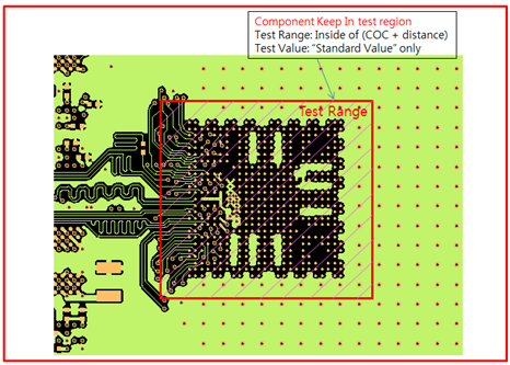
Figure 2. - Case2: Component Keep Out region test
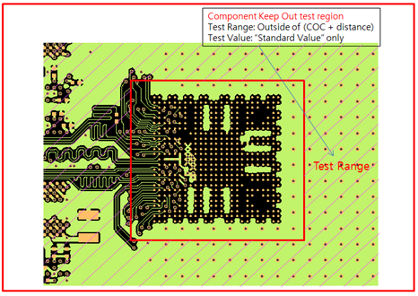
Figure 3. - Case3: Component Keep Out with extended region test
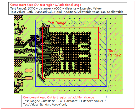
Figure 4.
- Case1: Component Keep In region test
Check Options
- Minimum clearance between differential pair nets: Specify minimum distance
between differential pair net group.
- Use Width Value (W): The value in Net Clearance and is considered as multiple of Pattern Width.
- Shield Distance: Specify the maximum distance of each Differential Pair Net
to the ground.
- Use Width Value (W): Upon selecting this option, the value in Shield Distance is considered as multiple of Pattern Width.
- Maximum: Specify maximum clearance from net to ground. If shield net exists father than this clearance, it reports fail.
- Minimum: Specify minimum clearance from net to ground. If shield net exists closer than this clearance, it reports fail.
- Tolerance (%): Measurement tolerance for Shield Distance.
- Display each segment error: Show all of failed points for every segment.
- Guard Via Distance Check: When an empty raw is double clicked, a Guard Via
Distance Check dialog opens. The DFE check maximum via distance of shielding net.
- Guard Via check range from target Net: Define the maximum distance from trace edge within which guard via should be exist. The DFE considers only the vias within this range as a guard via.
- Maximum Via separation: If the via distance is greater than this value, it is reported as failed.
- Except PAD: Exclude pin pad for testing.
- Display all the results of same net at once: PollEx DFE shows the merged result of all errors on the same display.
- Exclude Options
- Pin Escape: Enter a radius of circular region around pins to be excluded for the rule check.
- Via Escape: Enter a radius of circular region around vias to be excluded for the rule check.
- Exclude ARC Area: Exclude ARC shape area for testing.
- Exclude Serpentine Area: Exclude Serpentine shape area for testing.