If there is an EMI problem, one of the methods to correct the problem is to shield
with ground patterns. However, in most complicated designs, a perfect shielding is
not easy to accomplish. Therefore, designers should carefully design grounds to
achieve the best shielding effect not only for a single net but also for a
differential pair net. Differential pair nets are employed to resolve SI noise,
return path, PI, EMI issues that appear often in high speed signal nets. While
differential pair nets take care of return path and impedance issues by themselves
by being side-by-side with uniform distance apart, noise from other nets may disturb
the differential pair nets, if they are not properly shielded, then prevent the
paired nets do the intended roles. Therefore, it is important to shield the
differential pair nets as much as possible. In order to shield signal nets or traces
on the same layer, shielding grounds cover around the signal traces with a certain
uniform clearance. However, for differential pair nets, shielding grounds should not
present between the two pair nets. As a rule of thumb, it is recommended to shield
at least 80 percent of signal net length. This item checks whether a design meets a
specified shielding ratio.
Item: Input item name.
Check Type: Define the shield checking method of net.
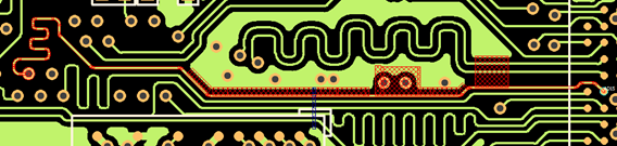
Separate Net: PollEx DFE detects existence
of shielding net(s) within specific distance per every segment. The
DFE regards only the portion of shielding net which is parallel with
target differential net.Figure 1.
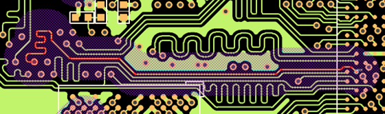
Merged Net: The DFE extends the searching area with the same amount
of specific distance, then PollEx DFE
detects existence of shielding net(s) within that region. This
method is more accurate than the Separate Net method, but it takes
more time. Figure 2.
Net: specify a differential net group.
Filter: Enter a filter to choose differential pair net from selected net
group.
Shield Net: High speed signal will be shielded with nets in this Shield net
group.
Component Keep IN/OUT: Define test region. For example, you can test inside
or outside the breakout region of CPU with different test
values.
Component Group: Select the required component group which is used
for defining the test region.
Region: Define the required test region.
IN: Test inside of the breakout region of target
component.
OUT: Test outside of the breakout region of target
component.
Range (COC+distance): Enter the distance value to define breakout range. The
COC (Component Overlap Check) plus this distance value is considered the
test range.
H-Shield Check: Option for horizontal shield check.
Horizontal Shield Ratio Check
Shield Distance: Specify distance from differential pair net to ground.
Use Width Value (W): Upon selecting this option, the value in
Maximum Shield Distance is considered as multiple of Pattern
Width.
Max: Specify maximum distance from differential pair net to ground.
The DFE searches shielding net within this range.
Min: Specify minimum clearance from net to ground. If shield net
exists closer than this clearance, it reports as a fail.
Min Horizontal Shield Ratio(%): Minimum shielding net length ratio against
total net. If the shielding ratio is smaller than given value, it is
reported as failed.
Ratio = The total length of shielded portion of
net/Total length of net
Shield Ratio Calculation Type: Determine shield ratio calculation method.
All Layer: Calculate shield ratio for total net.
Per Layer: Calculate shield ratio per each layer.
Exclude/Include Option:
Pin Escape: Enter a radius of circular region around pins to be
excluded for the rule check.
Via Escape: Enter a radius of circular region around vias to be
excluded for the rule check.
Exclude Short Pattern: Exclude the short length trace shorter than
this value.
Include trace corner: The ground shield length at which signal bend
is always longer than signal trace length. This leads to results
that are not accurate. In order to eliminate this problem, the DFE
ignores the bending position. The DFE includes the bending position
when calculating shield ratio.
Include Inner VIA Shielding: In the case of Inner Layer VIA where
the net is not connected, check the shielding.
Guard Via Distance Check
The DFE check maximum via distance of shielding net.
Guard Via Range: Define the maximum distance from trace edge within which
guard via should be exist. The DFE considers only the vias within this range
as a guard via.
Max Via Distance: If the via distance is greater than this value, it is
reported as failed.
Except PAD: Exclude pin pad for testing.
Merge Result Via Count: PollEx DFE shows the merged
result of all errors on the same display.
Min Vertical Shield Ratio(%):Minimum ground shielding ratio. If the
shielding ratio is smaller than the given value, it is reported as
failed.
Ratio = Shield Area/Net Area
Shield Ratio Calculation Type: Determine test layer.
All Layer: Calculate shield ratio for total net.
Per Layer: Calculate shield ratio per each layer.
Exclude/Include Option
Check Layer:
L1 Layer: check one layer above and below.
L2 Layer: check two layers above and below.
L2-Hop Layer: check two layers one layer apart above and
below.
Pin Escape: Enter a radius of circular region around pins to be
excluded for the rule check.
Via Escape: Enter a radius of circular region around vias to be
excluded for the rule check.
Exclude Short Pattern: Exclude the short length trace shorter than
this value.
Consider both upper and lower direction: Upon selecting, above and
below layer will be tested if not wider layer side will be checked
(above or below)
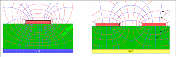
The flux radiated from each of differential signals are canceled each other because
of their polarity is reverse. But it still needs ground shielding for better EMI and
signal return. Figure 3.
Although crosstalk noise on a differential pair has a significant common-mode
component, it also has a differential component because the distance between an
aggressor and each side of the pairs differs. Consequently, each leg will experience
slightly different crosstalk, which will not be rejected by the differential
amplifier. The signal swing of differential signal is so small this crosstalk can
cause failure. Ground shielding is needed for differential lines.
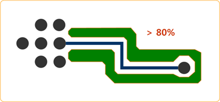
High speed signal’s 100 percent ground shielding is perfect, but it is impossible.
Over 80 percent and shielding for all routed layers are recommended. Figure 4.