Comp Thermal Condition
At this menu, you can define different analysis conditions for references on PCB design. Each line contains a component’s parameters.
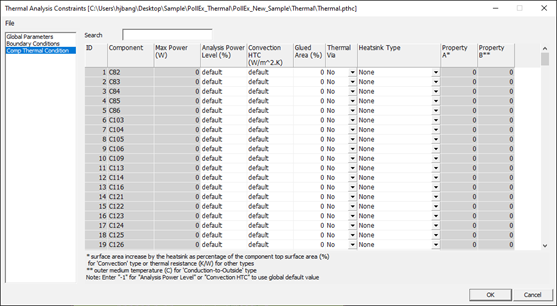
Figure 1.
ID: References’ index ID.
Component: Identifier on PCB design (Reference Name).
Max Power (W): Maximum power assign in UPF library (Not editable value).
Analysis Power Level (%): You can change this value depending on the components’ power usages. Default is 80% of assigned power at UPF file in part library.
Convection HTC (W/m^2.K): At component’s top side, if there is special conduction condition, specify the component top side convection heat transfer coefficient.
Glue Area (%): At component’s top side, if there is glued structure, define them with ration regarding to component top side area.
Thermal Via: If there are used thermal via under component bottom side, check Yes.
Heatsink Type: Choose the component heat-sink type among Convection, Conduction-to-Outside and Conduction-to-Board. Depending on the choice of this value, following columns’ values may change their meanings.| Heatsink Type | Property A* | Property B* |
|---|---|---|
| Convection | Surface Area increased by Heat-sink (%) | NA |
| Conduction-to-Outside | Thermal Resistance (K/W) | Outer Medium Temperature (C) |
| Conduction-to-Board | Thermal Resistance (K/W) | NA |
- Property A*: refer to above description.
- Property B**: refer to above description.