Thermal Analysis
The Analysis > Thermal Analysis menu allows you to run board level thermal analysis and review the results. A large-scale 3D finite element mesh for individual components and the board are automatically generated by the program. This board level thermal analysis can be effectively used to evaluate thermal performance of the PCB assembly throughout design stages and provide thermal boundary condition requirements for system level thermal design.
Thermal Analysis Run
The Analysis > Thermal Analysis > Thermal Analyzer menu is used for running thermal analysis. The thermal analysis control parameters and thermal boundary conditions defined in the Thermal Analysis Constraints dialog is applied to the analysis. Upon launching the menu, the thermal analysis emulation window opens, and built-in thermal analysis engine is executed.
Thermal Analysis Result Review
Upon completing thermal analysis run, PollEx Thermal automatically displays the analysis results including temperatures at board locations and individual components. You can save the analysis results for a later review.
Board temperatures are shown as a temperature contour map. You can view the temperature distribution at the top or bottom surface of the PCB. The temperatures of individual components can also be displayed together with the board temperatures. Component temperatures at the top case, junction, and bottom case are available for the graphical display.
You can use the analysis result dialog to view the detailed temperatures, edit the design and analysis constraints, and rerun thermal analysis.
Thermal Result Dialog Parameters
- Thermal Analysis Constraints
- Review and edit thermal analysis constraints.
- Board
- Select board side for temperature display.
- Temperature Display Range
- Define temperature contour display range.
- Component
- Select component outline, reference designator, and temperature display options. In addition to the graphical display, component temperature values are listed in a table.
- Move Component
- Use to see the thermal effect of relocating components. Start is used to initiate moving individual components. The relocated components are listed in the table. End is used to exit from the component moving operation.
- Analysis
- Use to re-run thermal analysis.
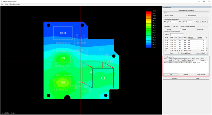
Figure 1.