Thermal Analysis Constraints Setup
Learn how to define thermal analysis constraints representing actual thermal operation environments of the PCB system.
Thermal Analysis Constraints is used for defining thermal analysis constraints, such as global and local thermal boundary conditions and local component thermal properties.
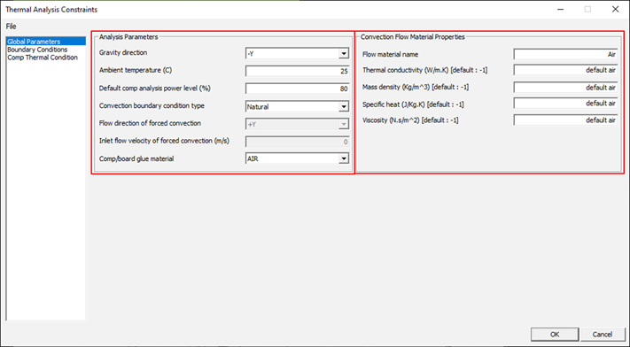
Figure 1.
Gravity direction: specify gravity direction (+X, -X, +Y, -Y, +Z, or -Z) of the board placed in actual operating condition.
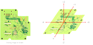
Figure 2.
Ambient Temperature
- Default component analysis power level: Specify default component power dissipation for analysis as percentage of the maximum power dissipated from component device.
- Convection boundary condition type: Select convection boundary condition type among natural and forced convections. Air, gas, or liquid can be used for the convection cooling.
- Flow direction of forced convection: Specify flow direction (+X, -X, +Y, or -Y) in case of forced convection condition.
- Inlet flow velocity of forced convection: Specify flow velocity at the inlet for forced convection condition case.
- Component/board glue material: Select a material to be used for bonding a component bottom surface to the board surface to improve thermal flow between the component and board.
Convection Flow Material Properties
For convection boundary condition, you can define properties of the convection flow material which can be air, gas, or liquid. The flow material properties include the thermal conductivity, mass density, specific heat, and viscosity. The properties of air at sea level are used for the system default.
Boundary Conditions
Built-in and user-defined thermal boundary conditions can be managed using Analysis > Thermal Analysis > Thermal Analysis Constraints. Upon selecting this menu, the Thermal Analysis Constraints dialog displays. In the dialog you can review and modify thermal boundary condition properties in the Boundary Conditions tab.
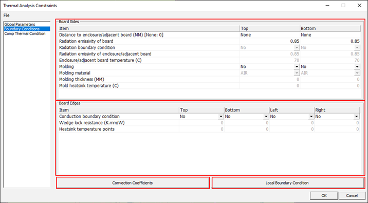
Figure 3.
You can define thermal boundary conditions at board boundaries including top and bottom board sides and top, bottom, left, and right board edges, as illustrated below.
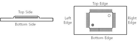
Figure 4.
Local Boundary Condition
To override the global boundary conditions, you can define local boundary conditions to specific board surface areas in the Local Boundary Condition menu. Add is used to define a new local boundary condition. For each board local boundary condition, the local board area outline shape (rectangle or circle), board side (top, bottom, or internal), location, size, and boundary condition data need to be specified. The area outline shape, location, and size can also be defined by drawing the area on the board after clicking Edit.
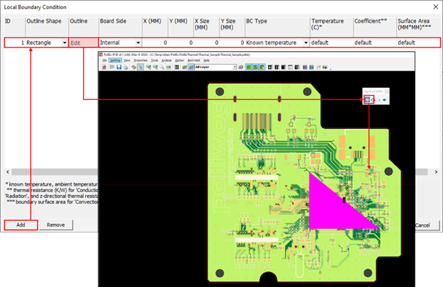
- Known temperature: known temperature
- Conduction: heat-sink temperature and thermal resistance to the heatsink
- Heat source: applied heat amount
- Convection: flow temperature, convection heat transfer coefficient, and surface area
- Radiation: outer medium temperature, effective radiation emissivity, and surface area
- Layer heatsink: z-directional thermal resistance
A heat source boundary condition can bealso be used for the condition of heat removal. In this case a negative value must be entered for the applied heat amount. The effective radiation emissivity is the radiation heat transfer coefficient obtained from considering the radiation emissivity values, sizes and view factor of the facing surfaces. A layer heatsink boundary condition represents a board area where solid planes are put in the signal layers to spread heat faster. This boundary condition is used only for a pre-route thermal analysis.
Component Thermal Condition
Globally defined thermal analysis control parameters and global boundary conditions are applied to all components on the board. Using the Local Boundary Condition tab in the Analysis > Thermal Analysis > Thermal Analysis Constraints menu, you can override the globally applied conditions for individual components by defining local conditions to the components.
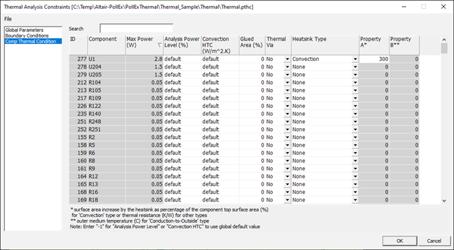
- Analysis Power Level: Component power dissipation for analysis as percentage of the maximum power dissipated from the component device.
- Convection HTC: Convection heat transfer coefficient to be applied to the component surfaces.
- Glued Area: Glued area as percentage of the component bottom surface area if the component is glued or bonded to the board.
- Thermal Via: Selection of whether thermal vias would be placed under the component or not. Used only for a pre-route thermal analysis.
- Heatsink Type: Type of the heat-sink attached to the component. The
available component heat-sink types and required data are:
- Convection: surface area increases by the heat sink as percentage of the component top surface area
- Conduction-to-Outside: thermal resistance from component top surface to outer medium and the outer medium temperature
- Conduction-to-Board: thermal resistance from component top surface to board