Boundary Conditions
If there are other thermal conditions on board side (Top/Bottom) or board edge (Top, Bottom, Left, Right), define them here.
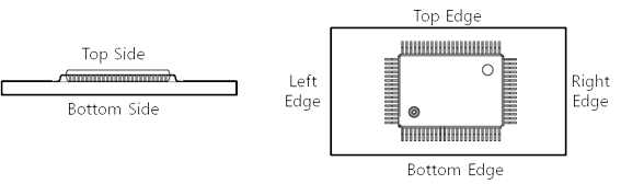
Figure 1.
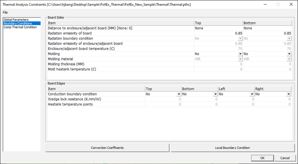
Figure 2.
Board Sides
Distance to adjacent board (MM) [None: 0]: If there is adjacent board, define the distance to adjacent board in unit, millimeter.
Radiation boundary Condition: If there is radiation boundary condition between board and adjacent board, set the value to Yes.
Radiation emissivity of board: If the value, Radiation boundary Condition is Yes, set the radiation emissivity of board.
Radiation boundary condition: If the radiation boundary exists, set this condition to YES.
Radiation emissivity of adjacent board: If the value, Radiation boundary Condition is Yes, set the radiation emissivity of adjacent board.
Adjacent board temperature: If the value, Radiation boundary Condition is Yes, set the board temperature of adjacent board.
Molding: If PCB is molded with some materials, you can define it.
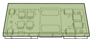
Figure 3. Molded PCB Board Shape
Molding material: If the value, Molding is Yes, select the molding material.
Molding thickness (MM): If the value, Molding is Yes, specify the molding thickness.
Mold heatsink temperature (C): If the value, Molding is Yes and is working with heat-sink, set the heat-sink temperature.
Board Edges
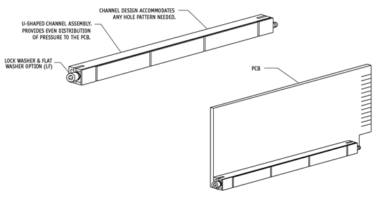
Figure 4.
Wedge lock resistance (K.mm/W): Specify resistance of wedge-lock.
Heatsink temperature points: Set number of points at which temperatures are assigned.
Convection Coefficients
If you want to assign different convection condition for some area, define them after dividing PCB into block. After making block, users can assign convection coefficient into block with values, flow temperature and heat transfer coefficient.
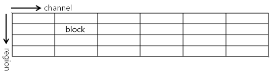
Figure 5.
Select each block and click Edit to change each block’s value.
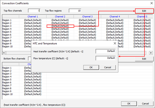
Figure 6.
Local Boundary Condition
For certain regions, if you want to assign special boundary condition on PCB design, use this menu. The Following image Figure 7 shows the way to make a region on PCB design.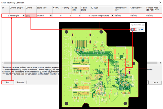
Figure 7.
After defining a region, define local boundary conditions. The Boundary Conditions of several parameters are filled in one line.

Figure 8.
ID: Boundary condition’s index ID starting from 1
Outline Shape: User-defined shape. User can input local region with two geometries, Rectangle or Circle.
Outline: Button menu to draw local boundary
Board Side: Board side on which local boundary placed.
X (Size) / Y (Size): Local boundary’s size
BC Type: You can select one of boundary condition type among Known Temperature, Conduction, Heat Source, Convection, Radiation and Layer Heatsink. Depending on the choice of this value, following columns’ values may change their meanings.
The following table shows other columns’ values depending on BC Type.
| BC Type | Temperature | Coefficient | Surface Area |
|---|---|---|---|
| Known Temperature | Known Temperature | NA | NA |
| Conduction | Outer Medium Temperature | Thermal Resistance (K/W) | NA |
| Heat Source | NA | Applied Heat (W) | NA |
| Convection | Ambient Temperature | Heat Transfer Coefficient (W/m^2.K) | Boundary Surface Area |
| Radiation | Outer Medium Temperature | Effective Radiation Emissivity | Boundary Surface Area |
| Thermal PAD | NA | Thickness (mm) | NA |
- Temperature: refers to above description.
- Coefficient: refers to above description.
- Surface Area: refers to above description.