Basic Menu Functions
Functions available in the net topology analyzer menus.
File
File menus are used for creating a new net topology analysis model, opening an existing model, or saving current model data. Upon executing New menu, you can enter the model name and select the net type among Single-ended, Differential and Multi-coupled. For multi-coupled nets, you need to enter number of nets in the model. After pressing OK, for Single-ended and Differential nets you are prompted to select a net topology to create among graphically shown common single-ended and differential net topologies.
According to the you selected net topology type, a driver, receiver, transmission line, and resistor element are automatically generated for each net of the newly created model. You need to define properties of each automatically generated element after selecting the element. You can edit the model by adding various types of elements to the initially generated model. Upon selecting Save menu, current net topology analysis model data is saved in Signal_Integrity/NTF directory under the PCB design job folder. The model name plus .ntfb is used for the file name. That model can be read using Open menu.
View
View menus enable you to control the graphical display of the model. The menus include zoom in, zoom out, window zoom, and fit window.
Properties
Properties menus enable you to view properties of materials, layer stacks, parts, transmission line models, and via padstacks. For layer stack, part, transmission line model, and via padstack data are shown for you selected design.
The transmission line models generated in Transmission Line Analysis are commonly used for all net topology analysis models of current design. Those models are listed in red color in Transmission Line Models menu and cannot be deleted or modified. In the menu, you can edit or create transmission line models. The transmission line models interactively or automatically generated in the net topology analyzer for current net topology analysis model can be used only for the net topology analysis model.
Edit
In Edit mode, you can select existing elements from graphical display to view the properties, change the properties, and delete them. You can add receiver pins, resistors, capacitors, inductors, connectors, single transmission lines, coupled transmission lines, vias, power supply nodes, ground nodes, merged nodes, and probes to the net topology analysis model.
- Driver Pin: PCB ID, part name, reference designator, pin name
- Receiver Pin: PCB ID, part name, reference designator, pin name
- Single Line Trace: PCB ID, model name
- Coupled Line Trace: PCB ID, model name, length, conductor ID, coupling ID
- Resistor: PCB ID, part name and pin names or resistance, reference designator
- Capacitor: PCB ID, part name or capacitance, reference designator
- Inductor: PCB ID, part name or inductance, reference designator
- Connector: Connector ID, model file, input port, output port
- Via: PCB ID, via padstack name
- Probe: PCB ID, probe name
- Merged Node: PCB ID, node name
- Power: PCB ID, supply voltage
- Ground: PCB ID
Probe elements are used to obtain waveforms anywhere in the net topology other than the output (driver) and input (receiver) nodes. Merged nodes with identical node names represent the same node. They can be effectively used for describing loop structures within single-ended nets or terminators directly connecting differential net pairs.
In the net topology analysis model, each net topology is shown in tree structure starting with an active driver pin. The other output and bi-directional pins in the net become receiver pins.
Analysis
Network Analysis menu under Analysis allows you to analyze the net topology analysis model in time and frequency domains to obtain the transient waveforms, eye diagrams, and frequency-dependent network parameters which are different views of the signal delay and distortion. Before analysis you can select an analysis type among Waveform, Eye Diagram, and Network Parameter and edit the input signal, device model selection, and analysis control parameters.
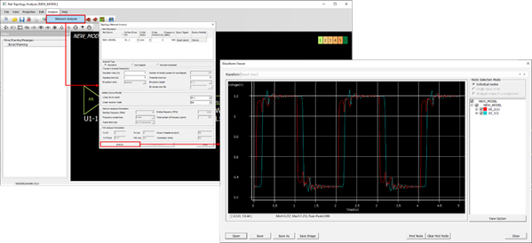
Figure 1.