Place Menu
After power integrity analysis, analyze the effect after making corrections such as reinforcing the plane, adding VIAs or adding some capacitors.
Decap Type Options
- VRM: You can add one capacitor near VRM component. The default name of VRM capacitor is adding C character before the reference name of the source component. (for example, CCN3)
- Port: You can add one capacitor near Load component. The default name of Port capacitor is adding C character before the reference name of the load component-pin number. (for example, CU204_R9)
- Distributed: You can add distributed capacitor to any location. The distance between the distributed capacitors can be controlled with X Spacing and Y Spacing options. The default names of distributed capacitors are adding C character before the coordinate of the capacitor. (for example, CX0.9Y39.9).
- Place prohibit zone : This function establishes a designed range of distance
from the center of the Via where the decap component is not allowed to be
positioned, thus preventing any overlap between the decap and Via. (for
example, prohibit zone range 0.5mm)
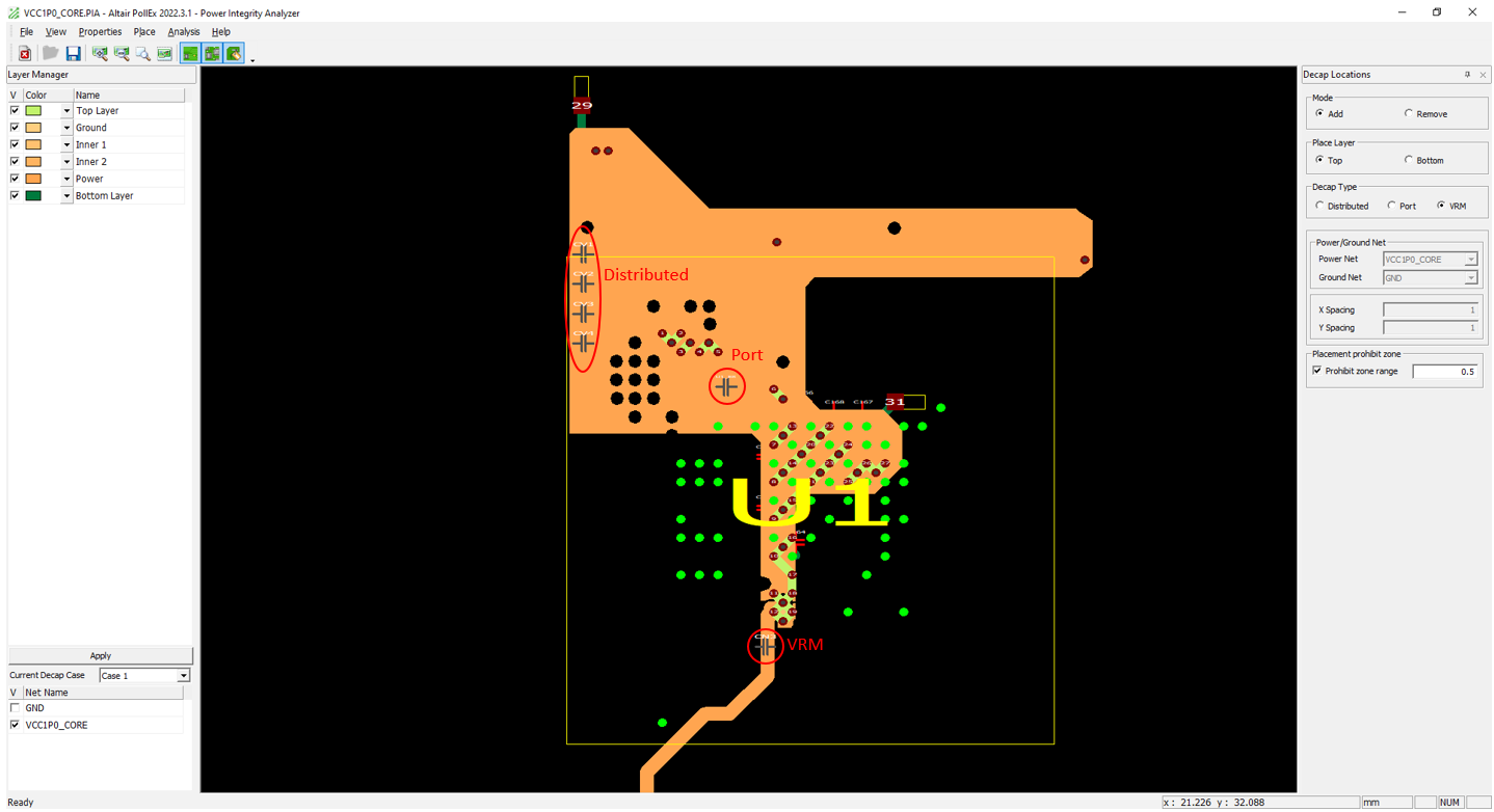
Figure 1.The default color of newly added capacitors are gray, gray color means that this capacitor has been positioned but no value has been assigned. The color of the capacitor changes to red after a capacitance value is assigned.
You can assign different values for each test case for the capacitor at the same location.
- Case: Change current test case. The capacitor value is assigned to the currently selected test case.
- Add Case: Add new test case.
- Decap to Use: Select the required capacitor value to be assigned.
- Assign to Individual Decap Locations: Assign capacitor value by clicking each capacitor. This menu operates in toggle mode.
- All Selection Option: Select required Decap Type.
- Assign to All Decap Location: Using this option, you can assign capacitor value to selected Decap Type capacitors at once. This menu operates in toggle mode.
Cleanup Expand the polygon around the VIA as much as the VIA Anti-Pad Size under the
following conditions.
- VIA in Plane Edge
- VIA in the Edge of VOID
- VIA placed closer than Anti-Pad Size