Nets
Net properties are basic attributes influencing the electrical analysis.
The voltages assigned to the Power/Ground net will be applied to the connected terminator pin as termination voltage. Net pairs defined as Differential Signal Positive (+) & Negative (-) will be recognized and simulated as differential pair by just assigning the driver model to one of both Positive (+) or Negative (-) net. The Properties > Nets menu will invoke a dialog with default net properties as Single-ended signal for all nets included in the activated PCB system, by double-clicking a net or selecting a net and clicking Edit, you can define or modify the Net Type, Voltage, and electrical constraints. By clicking Pin list, you can verify the list of all pins connected to the selected net.
By clicking Assign Net Type, you can set net property automatically using net information described in IBIS files and property.
By clicking Find Net Class, you can set net class automatically using pre-defined net class search string file.
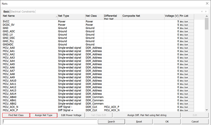
Figure 1.
Composite Nets
When two or more nets are serially connected through passive components such as resistor, electrical analysis must be made for the entire signal path encompassing the multiple nets connected with these passive components.
 Figure 2. |
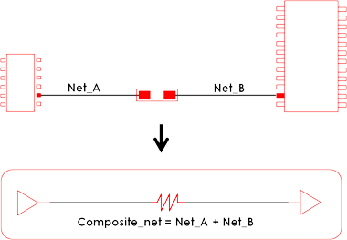 Figure 3. |
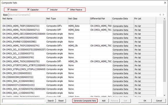
Figure 4.
In Composite Component Area, you can select components to be used to generate composite net. Two nets connected with this component are modeled as composite nets. After selecting composite component, the Generate Composite Nets function will list composite nets on the composite net result display region. Using the Add menu, you can manually specify the nets on which to composite.
You can remove or edit composite net result by clicking Remove or Edit. By double-clicking one of composite net, the Edit dialog will be displayed. You can change Net Type, Net Class and Electrical Constraints.
In the Composite Data field, you can review the composite net connection structure.
In the Pin list field, you can review the component and pin number connected to the composite set.