
Tutorial: Stationary Quenching Analysis
Tutorial Level: Beginner Set up and run a stationary quenching analysis.
Open the Tutorial Model
- From the menu bar, select .
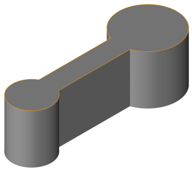
- Browse to your working directory, select dumbbell_profile.x_t, and click Open.
-
Position the model as shown.
- Set the display units to Metric (mm kg MPa C s).
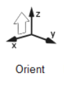
Orient the Model
Inspire Extrude assumes the extruded profile comes in a positive Z axis. These steps help to orient the profile in this axis automatically.
- On the ribbon, click the Quenching tab.
-
Click the Orient icon.
-
On the model, click the exit surface.
The model is oriented such that the profile is in the +Z direction.
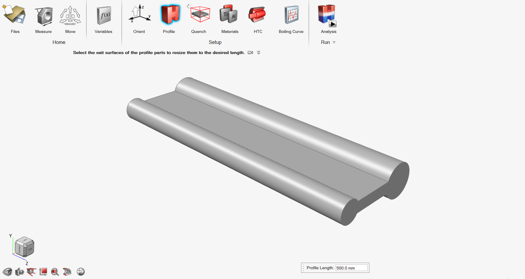
Create the Extruded Profile
The imported or created profile cross-section often does not have the desired length of the extruded profile, which is achieved in this step.
-
From the Quenching ribbon, click the
Profile icon.

-
On the model, click the exit surface as shown.
- Enter 500 mm for Profile Length.
Create a Quenching Zone
-
On the Quench icon, click the Create Quench
System satellite.

-
Click the Air Fan icon.
Depending on the interaction between cooling medium and material profile, various options are available. This tutorial will use air fan quenching. -
Change the quench box length L to 800
mm.
You can select which surfaces you want to put fans. For now, keep it default.
Figure 1. Quench Box Setting 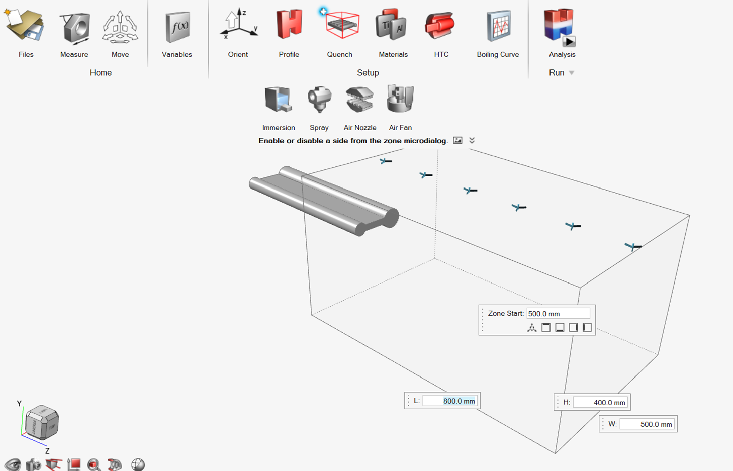
Note: The quench box should be large enough to cover the profile. Hence, the length of the quench box should be bigger than the profile length.The solver automatically puts the profile at the center of the quench box during simulation. You should not try to manually put the profile at the center. Instead, leave the zone start value as it is.
-
To open the fan settings, click on any of the fans shown in the quench
box.
Upon clicking the fan, the fan settings dialog box opens.
-
Select the following parameters:
- Number of Fans: 1.0
- Fan Diameter: 60.0 mm
- Fan Pitch: 400.0 mm
- Offset: 400.0 mm
- Flow Rate: 7000.0 LPM
- Temperature: 29.85 C
Figure 2. Air Fan Settings Dialog Box 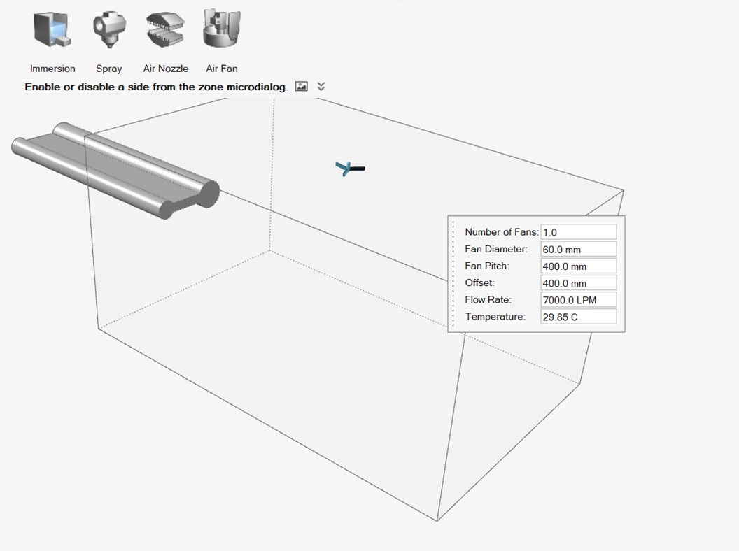
Review Material Properties
-
Click the Materials icon.

-
Ensure that you are using the default material data for this analysis.
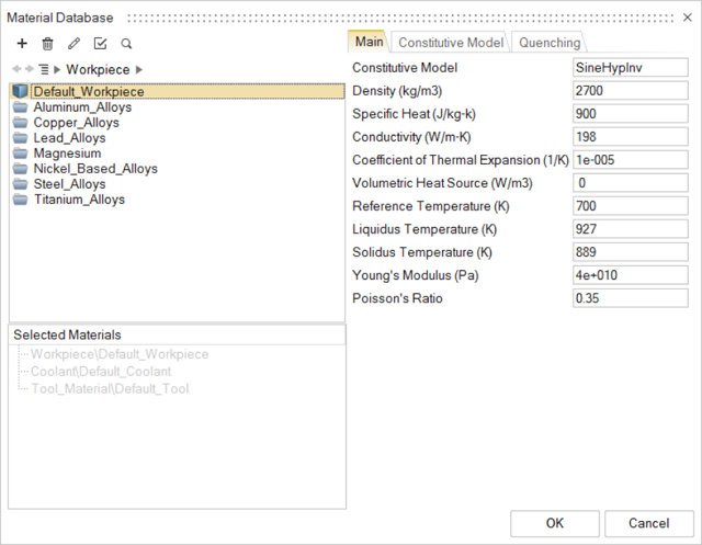
- Click OK to confirm.
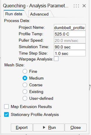
Run Quenching Analysis
- Save the model.
-
Click the Run Analysis icon.

- Select the Stationary Profile Analysis check box.
-
Enter and review the following parameters:
- Process Data:
- Project Name: dumbbell_profile
- Profile Temp: 525.0 C
- Puller Speed: 20.0 mm/sec
- Simulation Time: 90.0 sec
- Time Step Size: 1.0 sec
- Mesh Size: Medium
- Select the Stationary Profile Analysis check box.
- Process Data:
-
Click Run.
Review the Results
- When the analysis is complete, double-click the name of the run to open the results.
- In the Analysis Explorer, select the Temperature result type.
- Click the Play button on the animation ribbon.
- Select and animate the other result types.
-
Right-click to exit the Analysis Explorer.
Figure 3. Temperature Distribution Over Profile While Being Cooled 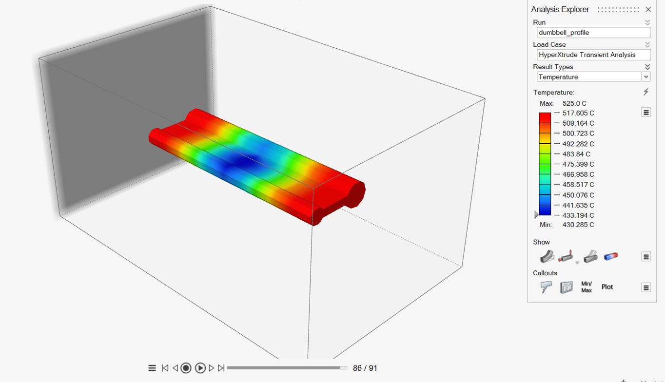
On the Analysis Explorer, various parameters such as temperature, cooling rate, and quench factor are available. Figure 3 shows the temporal evolution of temperature as the profile is being cooled.