Tutorial Level: Advanced Learn how to optimize the bearing profile by grouping bearing lines.
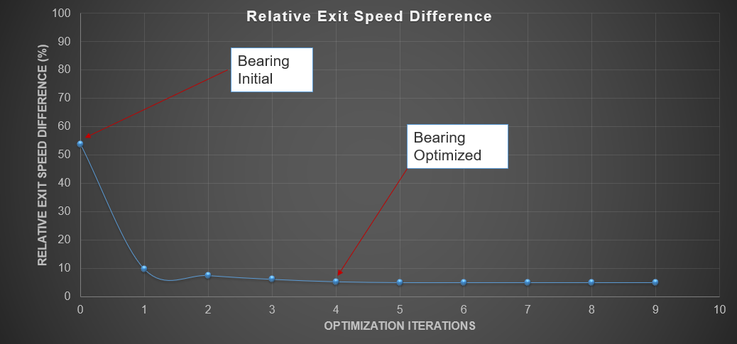
Bearing length optimization is performed to ensure the velocity of an extruding profile
at the exit is uniform. Before setting up for bearing optimization, the standard model
setup should be fully completed or ready for performing a steady-state analysis.
Load Model
Before you begin, copy the file(s) used
in this tutorial to your working directory.
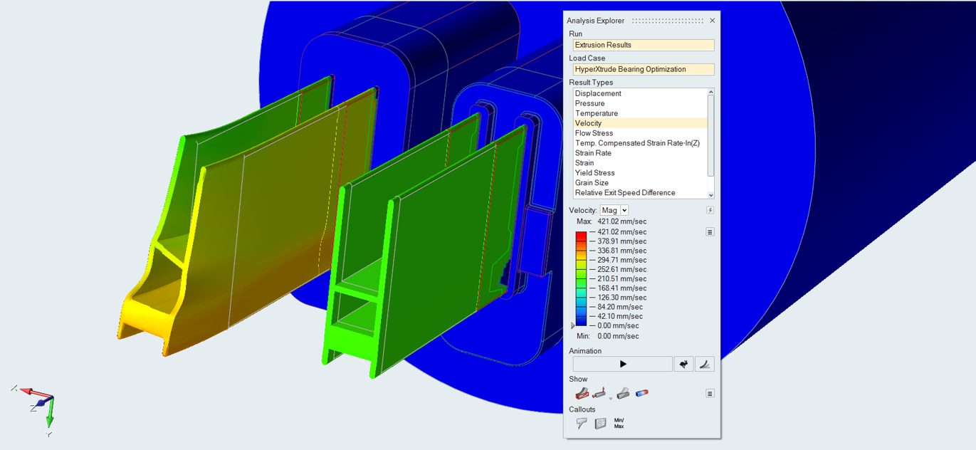
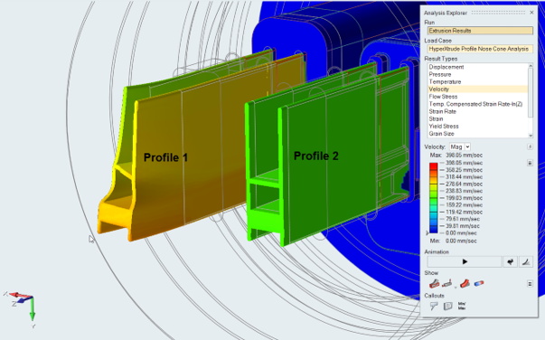
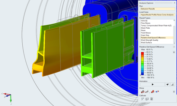
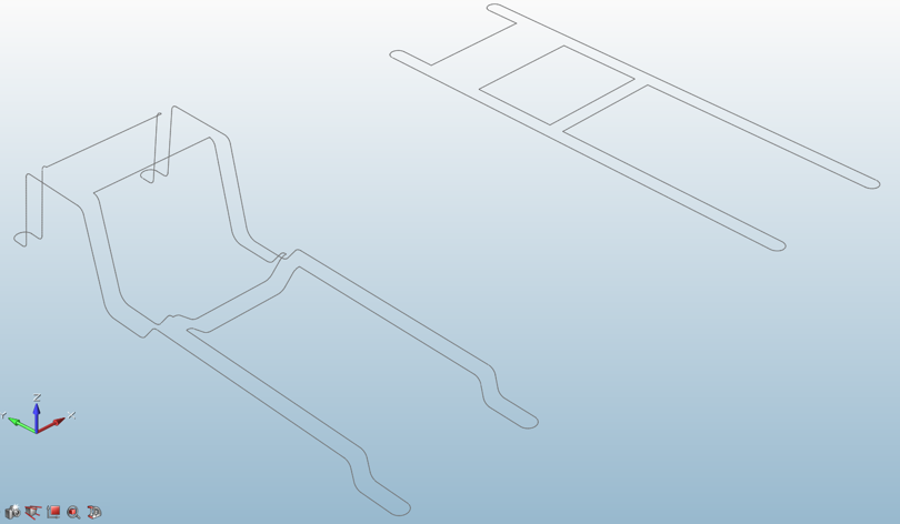
Profile 2 is balanced. Profile 1 is not balanced, and the extruded part is
going to bend. This tutorial will focus on the optimization of the bearing
length to correct this profile.
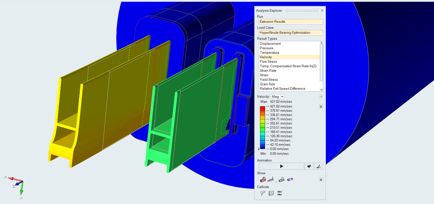
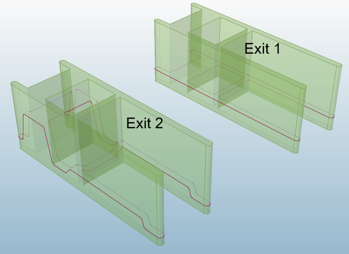
Review initial bearing lengths on both exits.
Exit 1 does not have correct bearings to get uniform flow, so we are going to
set optimization for it. Exit 2 already has correct bearing lengths, so we will
keep all bearing lines in this exit fixed.
Consider Grouping Bearing Lines
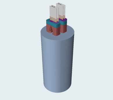
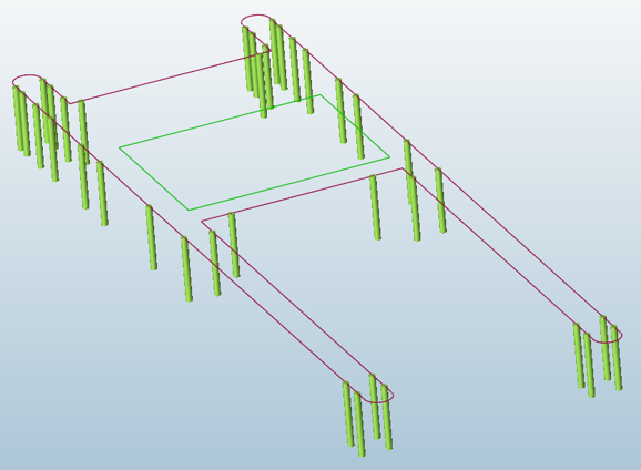
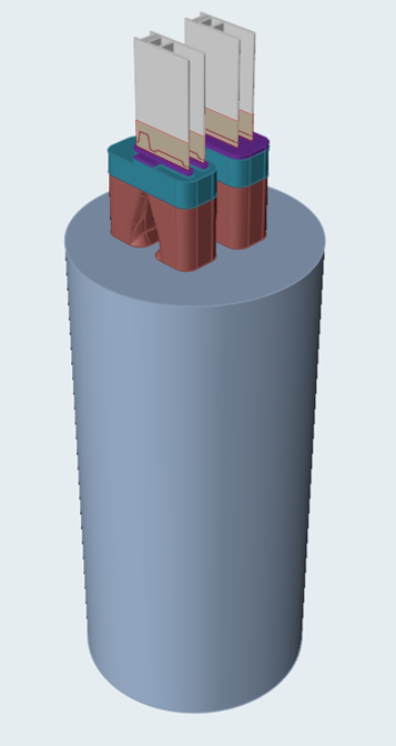
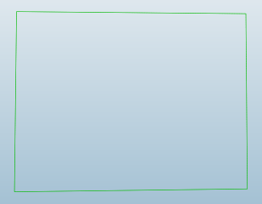
Review the die opening in the model.
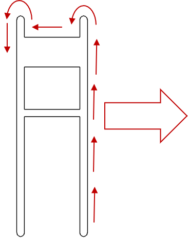
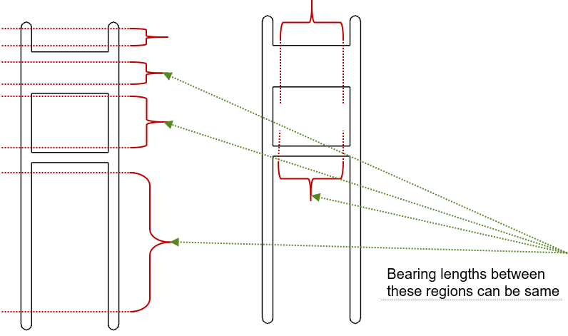
Check the wall gap opening.
For a bearing curve, if the wall gap opening is the same, then bearing lengths
can be the same. Based on this, control lines are grouped as shown.
This is the first level approach for deciding where to keep bearing lengths
the same. The next level of grouping bearing lines depends on how the pocket is
designed around the die opening and how the portholes are designed.
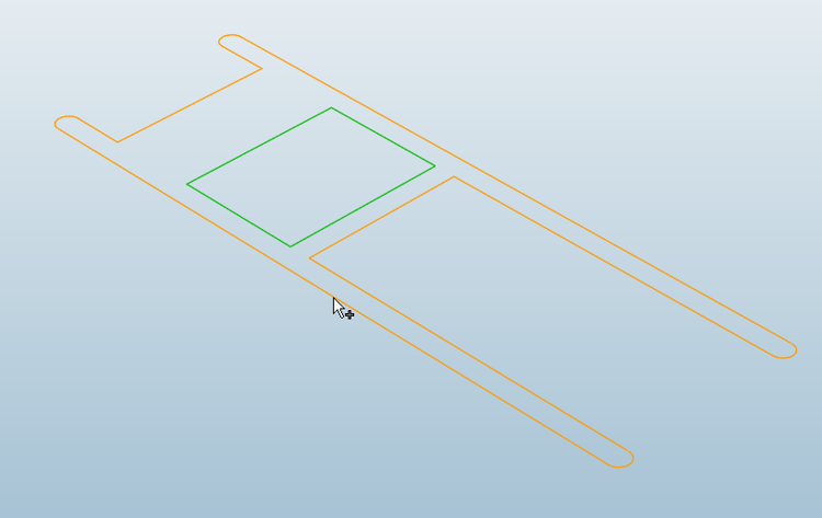
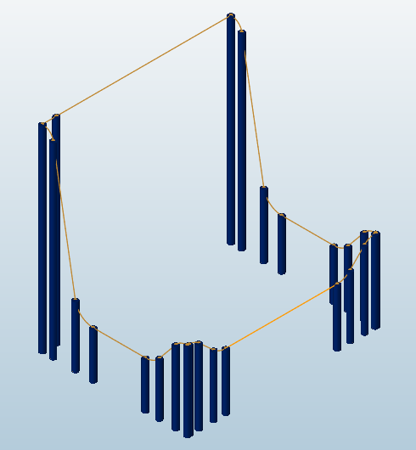
Select Bearing Curve
The goal of this interface is to classify bearing lines into different groups.
Lines in a group are assigned the same initial bearing length and are optimized
identically.
Click the Bearing Optimization icon.
Inspire Extrude will hide all components and
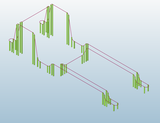
show all bearing curves in the model.
Click on a bearing curve to optimize.
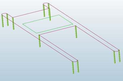
The first time this is done, vertical bearing lines for all of the curves are
created. This is a one-time operation. Be sure to let the process finish.
The selected curve will be displayed along with its extracted vertical
bearing lines.
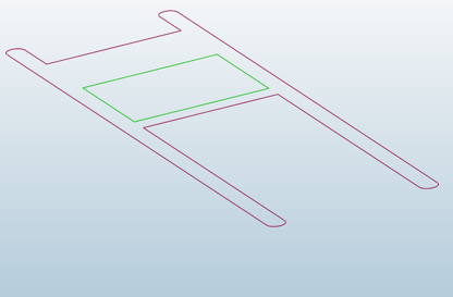
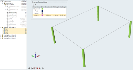
In the Model Browser, select these vertical bearing control
lines that are automatically created.
We are setting optimization for BearingCurve_1, and control lines for this
bearing curve will be in the BearingControlLines_1 component.
Right-click and select Delete.
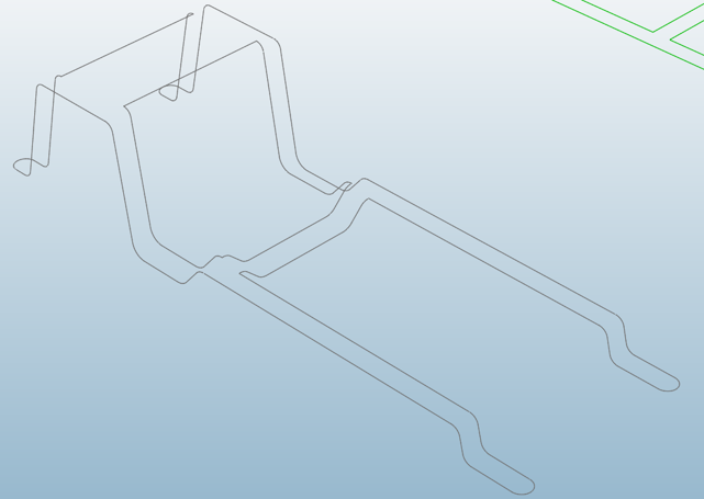
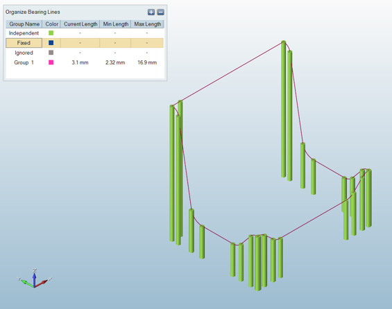
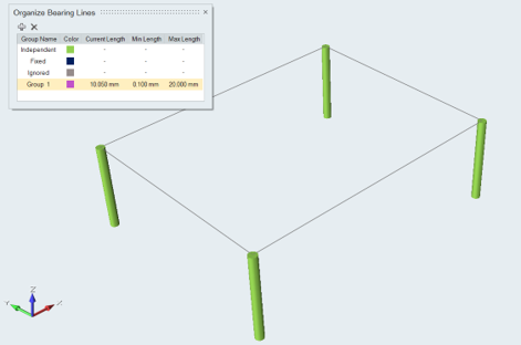
Add Extra Bearing Control Lines
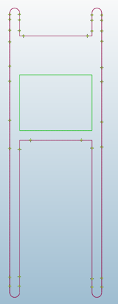
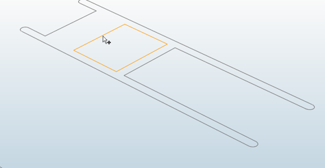
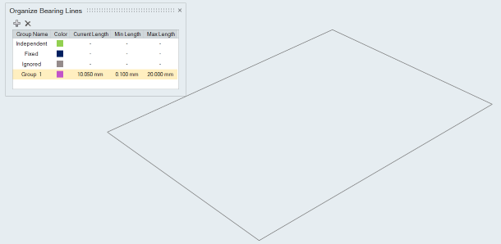
Position the model to the top view.
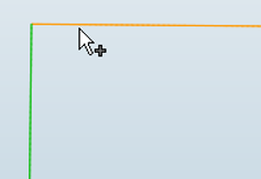
Hover over the bearing curve where you would like to add a new bearing line and
click to add.
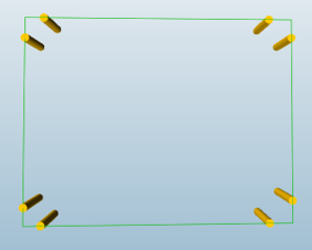
Repeat to add additional bearing lines on the bearing curve.
In this example, we have added 8 bearing lines, 2 on each of the 4
corners.
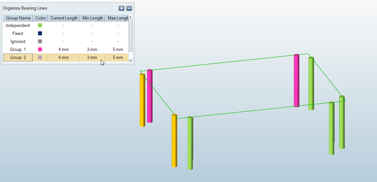
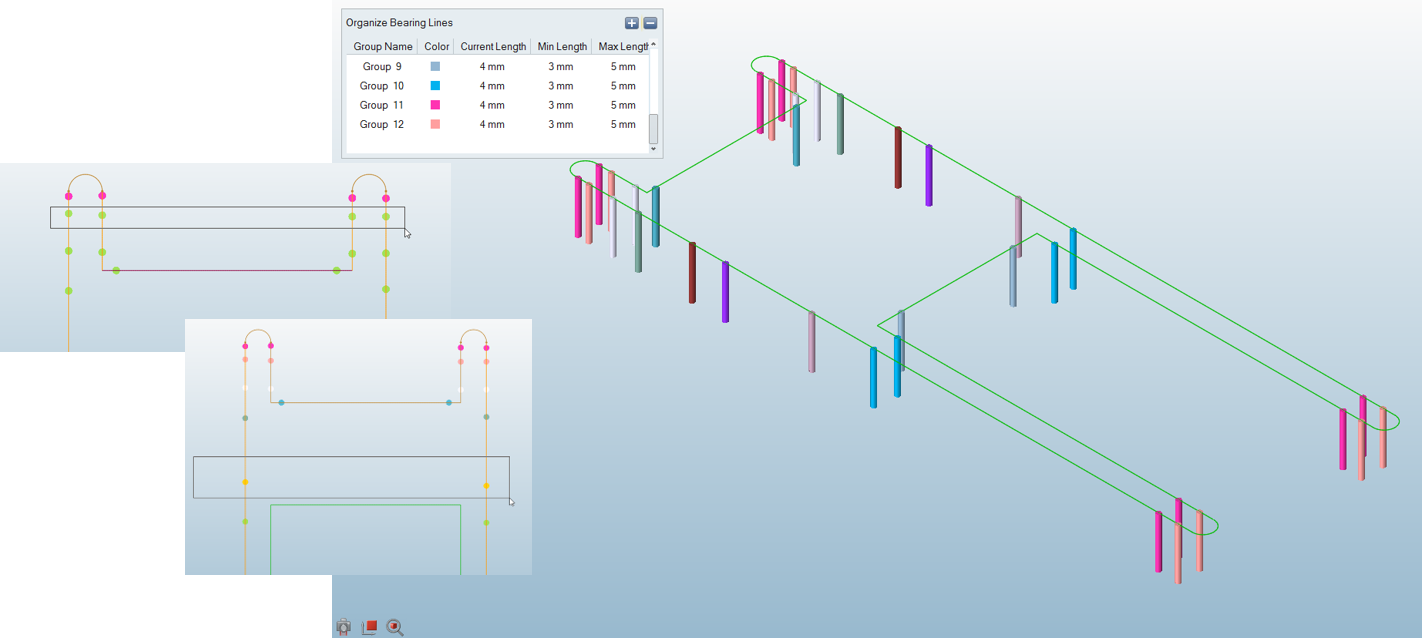
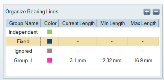
Group Bearing Lines
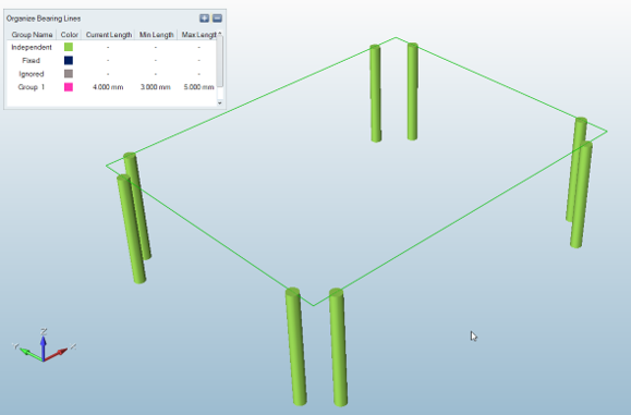
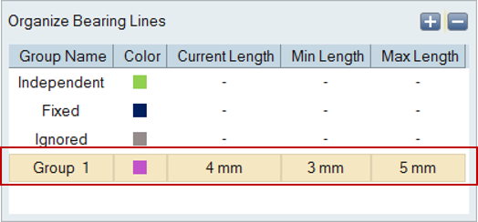
Select Group 1 in the Organize Bearing
Lines window.
Select bearing lines to be included in this group.
Here we are selecting the highlighted lines.
Double-click anywhere outside of the bearing zone to accept the
selection.
Click to add a new group, and select lines to be added to
this new Group 2.
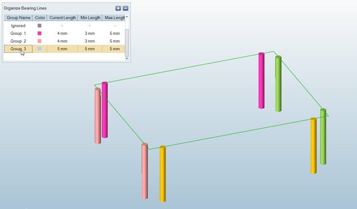
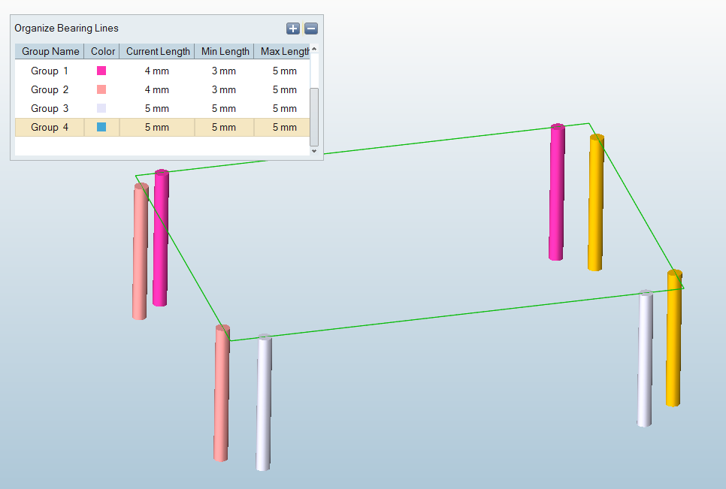
Repeat for Group 3 and Group 4
selecting remaining bearing lines.
Exit Optimization Panel by pressing
Esc key.
The full model is displayed.
Select Next Bearing Curve
Click Bearing Optimization icon.
Inspire Extrude will hide all components and
show all bearing curves in the model.
Select the outer bearing curve.
In the Model Browser, select these vertical bearing control
lines that are automatically created.
Right-click and select Delete.
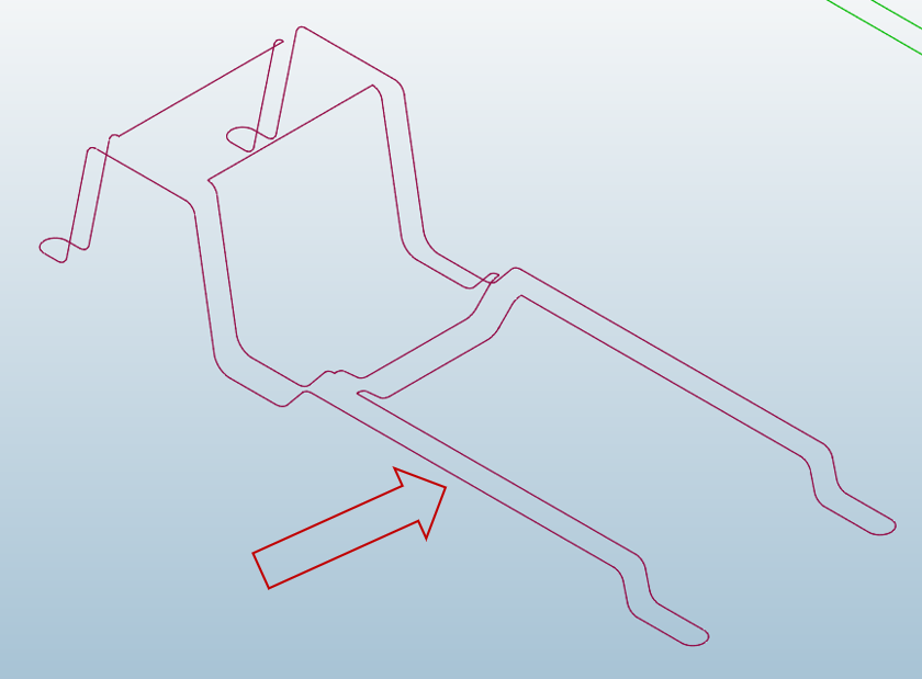
Add Next Bearing Control Lines
Position the model to the top view.
Hover over the bearing line and click to add the lines shown.
Group Next Bearing Lines
Select bearing lines to organize them into respective groups.
Note: You can select lines individually or drag to draw a box around a group of
lines.
Optimize BearingCurve_2
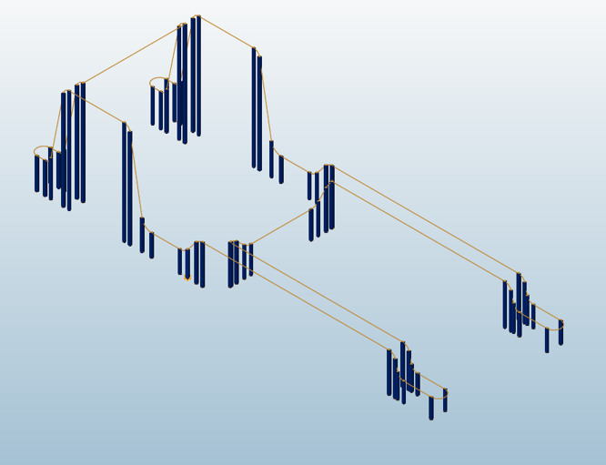
Since the following bearing is already optimized, we are going to group all of the
bearing lines as Fixed.
Select the outer bearing curve.
Click the Fixed group.
Select all of the bearing lines on the screen.
Click any empty area to accept the selection.
Optimize BearingCurve_3
We are going to continue to group all of the optimized bearing lines as Fixed.
Select the inner bearing curve.
Click the Fixed group.
Select all of the bearing lines on the screen.
Exit Optimization Panel by pressing
Esc key.
The full model is displayed.
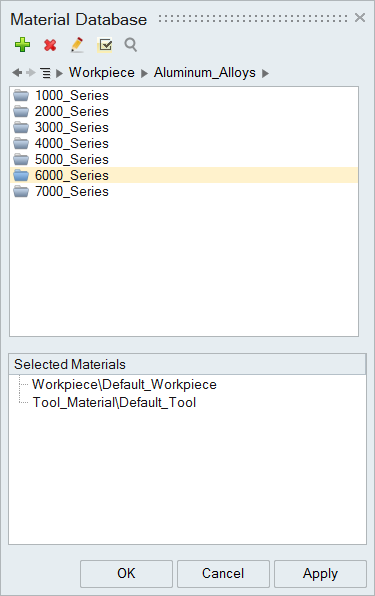
Select the Material
Click the Materials icon.
Select the Workpiece alloy Aluminum_Alloys > 6000_Series > AA6063
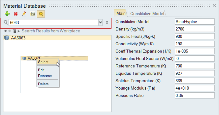
Note:
You can search directly for the material by clicking the search box
and typing the name of the alloy.
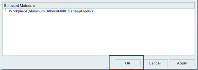
Right-click on the alloy name, and click Select.
The chosen alloy is added to the Selected Materials pane.
Note: To deselect a material there, right-click and click
Deselect.
Click OK to close the Material Database.
Click File > Save As to save the model at the desired location.
Note: It is recommended that you always save the model file in a newly created
folder to avoid conflict with older/existing model files.
Specify Process Parameters and Simulate
Click the Submit job for analysis icon to run the
simulation.
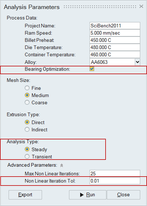
In the Analysis Parameters window that pops up, enter
values as shown.
Note: The Bearing
Optimization checkbox is shown. This check entry will only
be shown when the model has optimization data defined.
Note: Set Non Linear Iteration
Tolerance to 0.01 for bearing optimization and transient
simulations. Use 0.001 for steady state simulation.
Click the Run button.
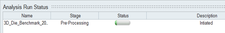
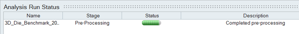
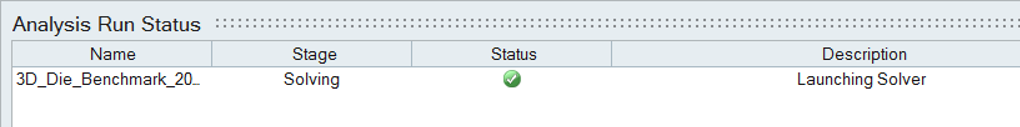
On successful launch of the run, you can monitor the status
of the simulation.


 to add a new group, and select lines to be added to
this new Group 2.
to add a new group, and select lines to be added to
this new Group 2.