Tutorial: Tool Deflection Analysis
Tutorial Level: Beginner Run a tool deflection analysis to determine where and how the tool is likely to deform during the extrusion process and help the die designer make corrections in the tool components accordingly.
Use tool deflection analysis to determine where and how the tool is likely to deform during the extrusion process and help the die designer make corrections in the tool components accordingly.
- Through coupled flow, thermal and stress analysis
- By writing a .fem file that contains tool mesh, material data, and BCs which can be submitted to OptiStruct solver for stress analysis
- Using the Tool Analysis Wizard in Inspire Extrude
The Tool Deflection Analysis Wizard has several advantages. The flow analysis and tool deflection analysis can be performed independently which helps in preventing the problem before it becomes too large. The analysis can be set up in a few steps.
- In the form of assumed temperature and pressures/forces on the
surfacesNote: Assumed pressure loads can be constant or vary linearly along the extrusion direction
- By mapping loads from a .hmascii file written by HyperXtrude while performing the flow analysis
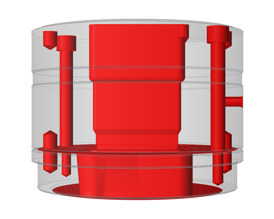
Load Model
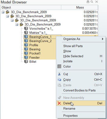
Delete Workpiece Components
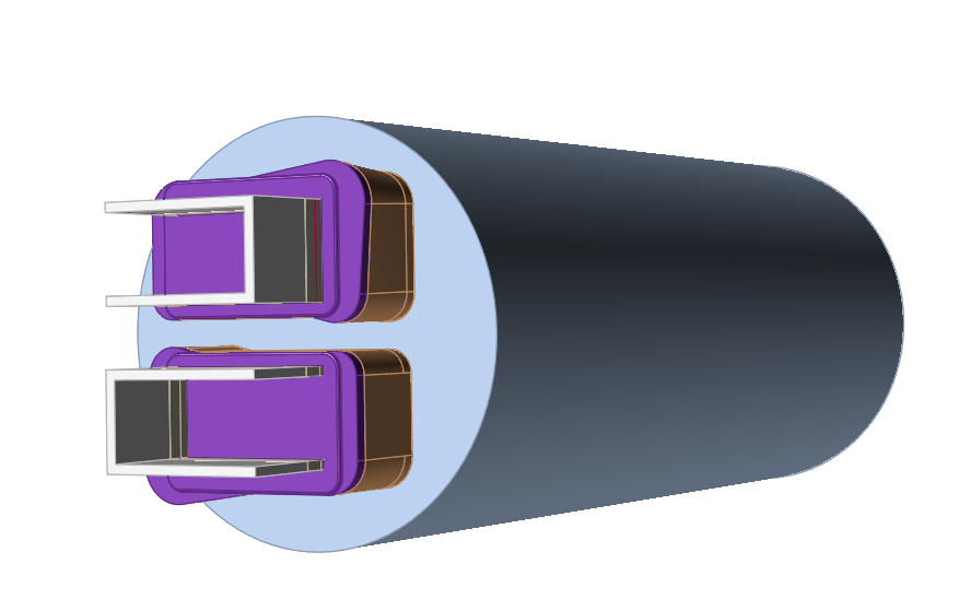
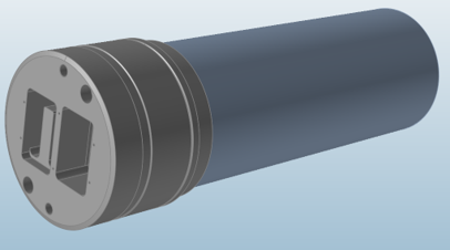
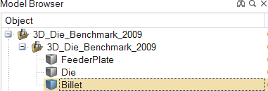
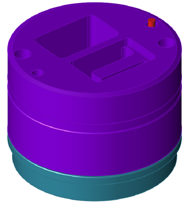
This model contains two tool components, the feeder plate and die plate, as well as workpiece components that are not required for tool deflection analysis. Those components should be deleted before proceeding.
- Open the Model Browser by clicking or by pressing F2.
-
Delete flow region components, except Billet, from the
model by selecting the objects then right-clicking and choosing
Delete.
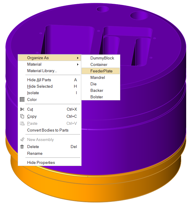
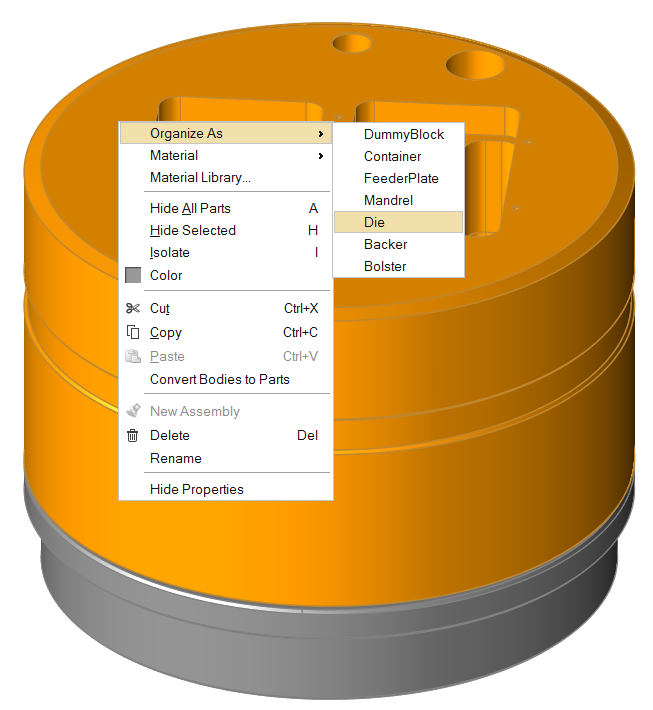
Organize Tool Components
This model contains two tool components, the feeder plate and die plate, which need to be organized.
- Click the Tool Deflection ribbon.
-
Right-click on the feeder plate solid, and select .
-
Right-click on the die plate solid, and select .
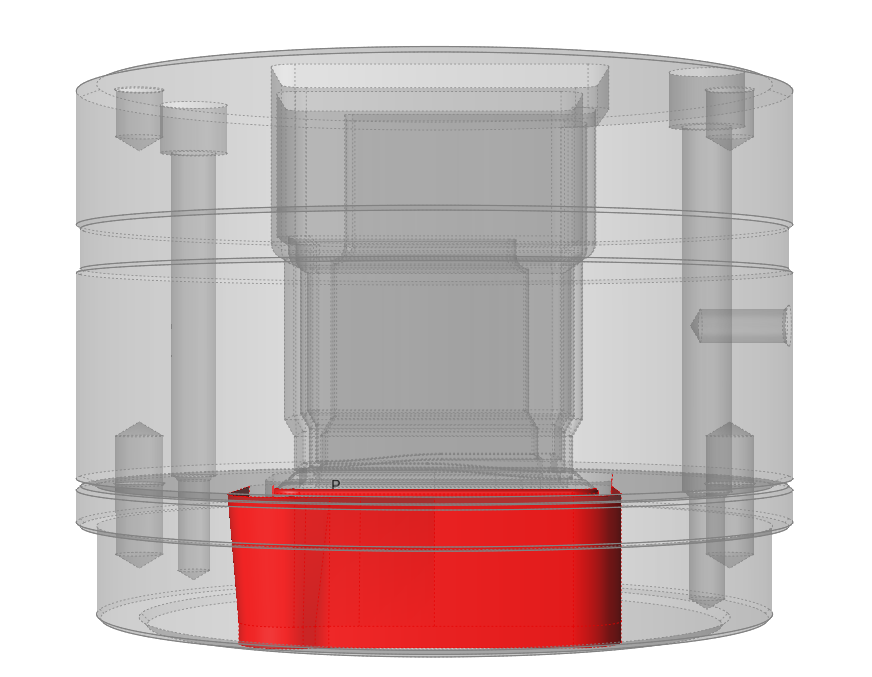
Simplify Geometry
The Simplify tools can be used to clean up problem areas in the geometry before running an analysis. They are used to delete extraneous lines, surfaces, and other components in the model and to remove unnecessary features such as holes used for instrumentation. This simplifies meshing and reduces the mesh size.
- Click the Geometry ribbon.
-
Click the Simplify icon.

-
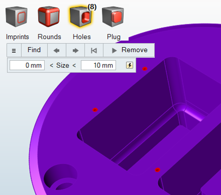
Click the Holes icon.

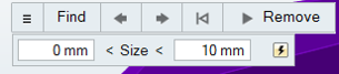
You can fill holes one at a time or detect holes smaller than a certain size to avoid filling incorrect areas. To detect holes smaller than 10mm, click Find Options and set the Maximum Size to 10mm. In this model, there are 8 holes which are not required.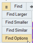
 The tool will automatically inspect the geometry and detect all holes in the model. This will also include voids for the flow region, too.
 -
Once the holes you would like to remove are highlighted, click
Remove to fill the holes.
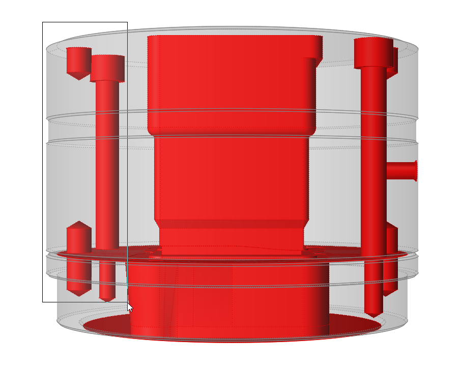
Create Load Faces
Create load faces where the material touches the tool geometry.
Workpiece material flowing inside the die exerts a load on tool surfaces and faces which are common between the workpiece and tool bodies. These are called load faces. Surfaces such as pin holes and relief regions are not in contact with the workpiece and should not be part of the load faces.
-
Click the Load Faces icon.

-
Press Ctrl and drag to draw a box to unselect a group of surfaces that are not in contact with flow material.
-
Repeat for the other surfaces.
Note: Make sure that only surfaces which are in contact with the workpiece remain selected.
- Right-click and mouse through the check mark to exit, or double-right-click.
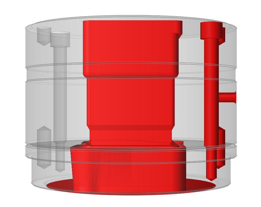
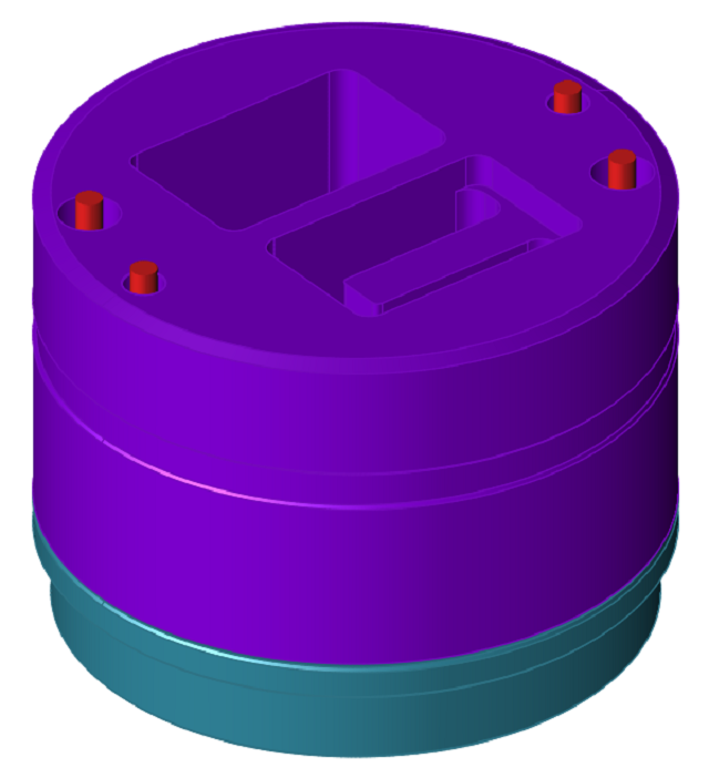
Create Constraints
The BCS tool is used to manually create constraints on appropriate surfaces.
-
Click the BCS icon.

-
Select a constraint surface.
-
Repeat the process for all constraint surfaces you wish to specify.
Select the Material
-
Click the Materials icon.

-
Select the Tool alloy
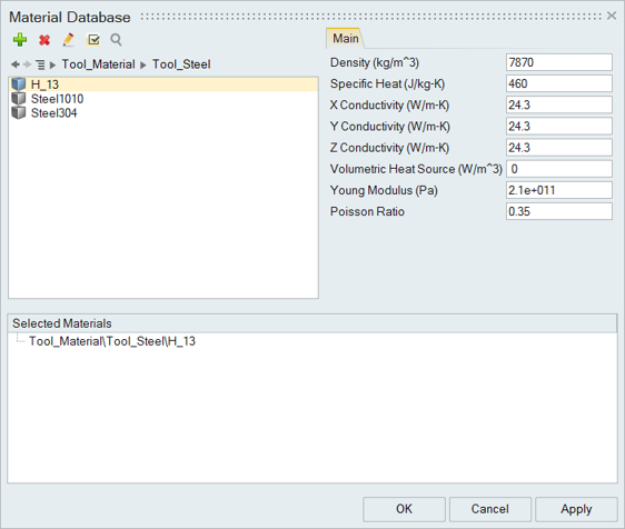
- Click OK to close the Material Database.
-
Click to save the model at the desired location.
Note: It is recommended that you always save the model file in a newly created folder to avoid conflict with older/existing model files.
Specify Process Parameters and Simulate
-
Click the Submit job for analysis icon to run the
simulation.

-
In the Analysis Parameters window that pops up, enter
values as shown.
Note: Select Mapped under Pressure Type and browse to the *.hmascii file from the tutorial folder. This file contains pressure and temperature load information from flow simulation.
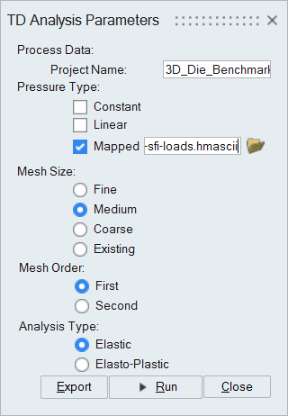
- Click the Run button.
| Status after submitting the job |
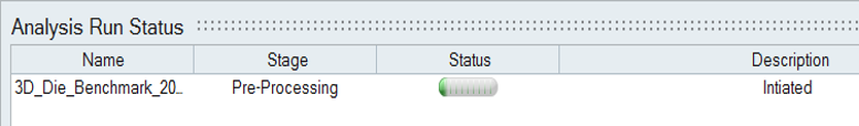 |
| Status after meshing is completed |
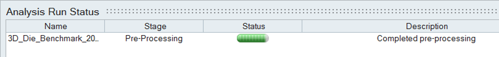 |
| Status when job is running in the solver |
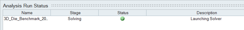 |
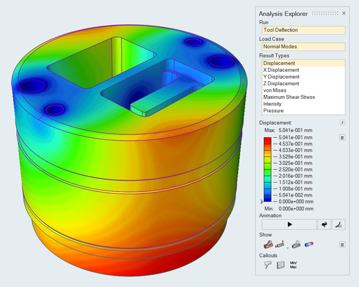
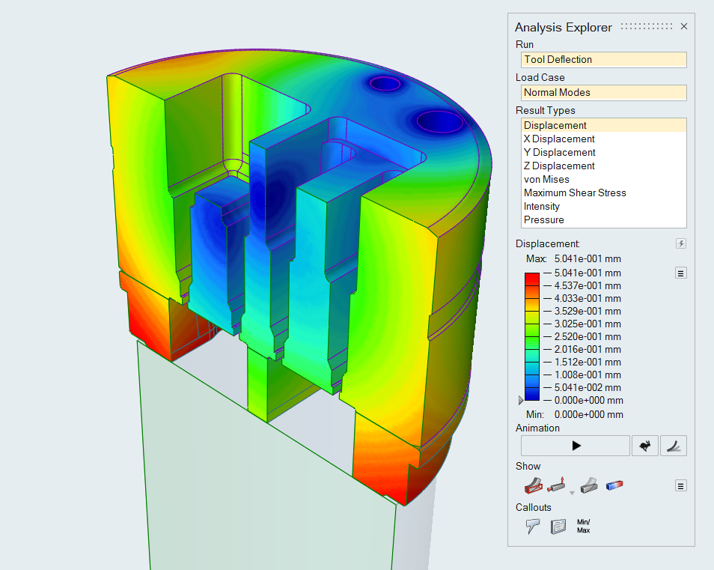
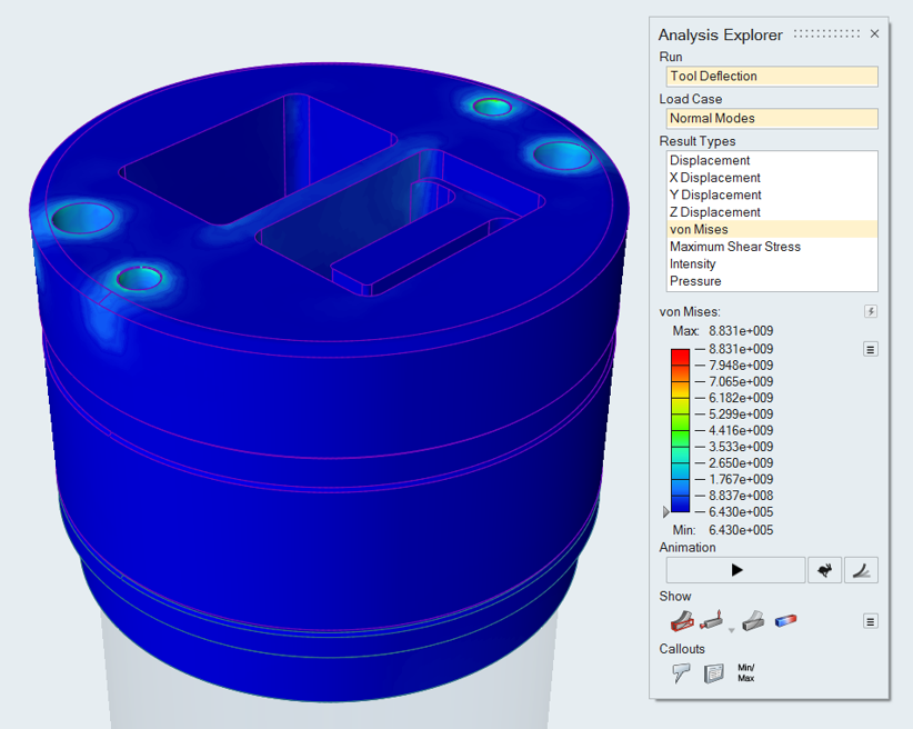
View Simulation Results