Browse to your working directory, select
SciBench2011_die.x_t, and click
Open.
From the menu bar, select File > Import.
Browse to your working directory, select
SciBench2011_mand.x_t, and click
Open.
Click the Extrusion ribbon.
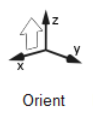
Click the Orient tool to position the model.
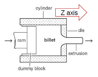
The die should be oriented such that the profile is coming out in the +Z
direction.
The center of the die face touching the billet is at X=0, Y=0, and Z=0
Click the exit face of the die assembly to orient the model.
The orient context is enabled.
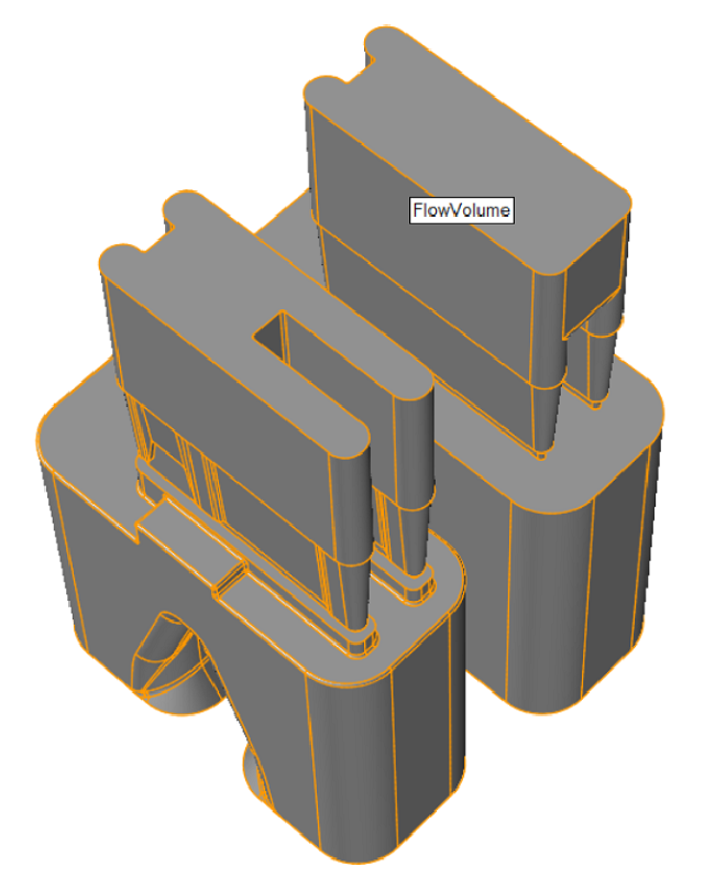
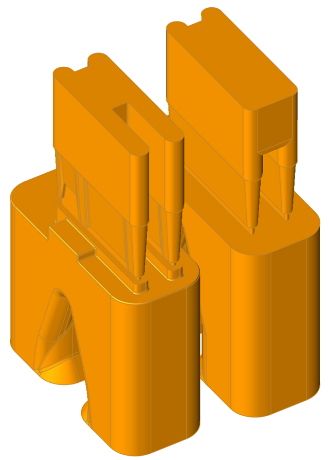
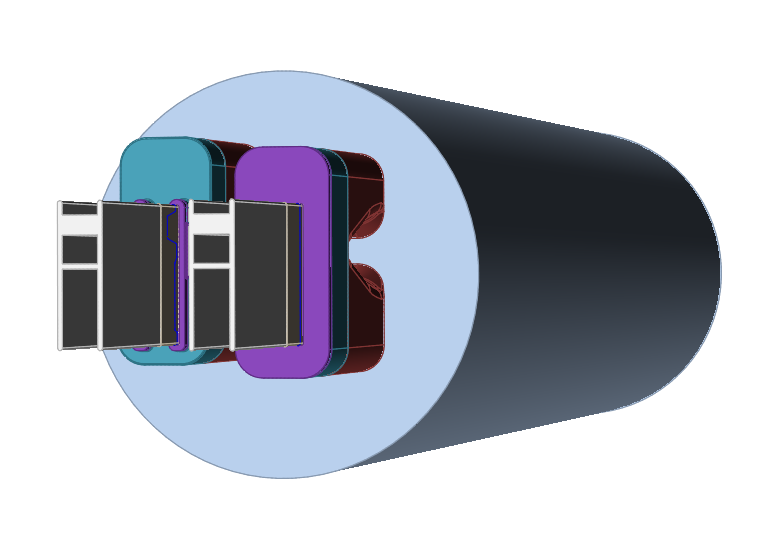
Extract Flow Volume
Click the Flow Volume icon to extract flow volume inside
of the die cavity.
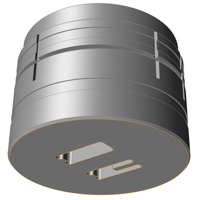
Click and hold left mouse button while you drag a box around all the die solids
as shown.
Release left mouse button to extract flow volume automatically.
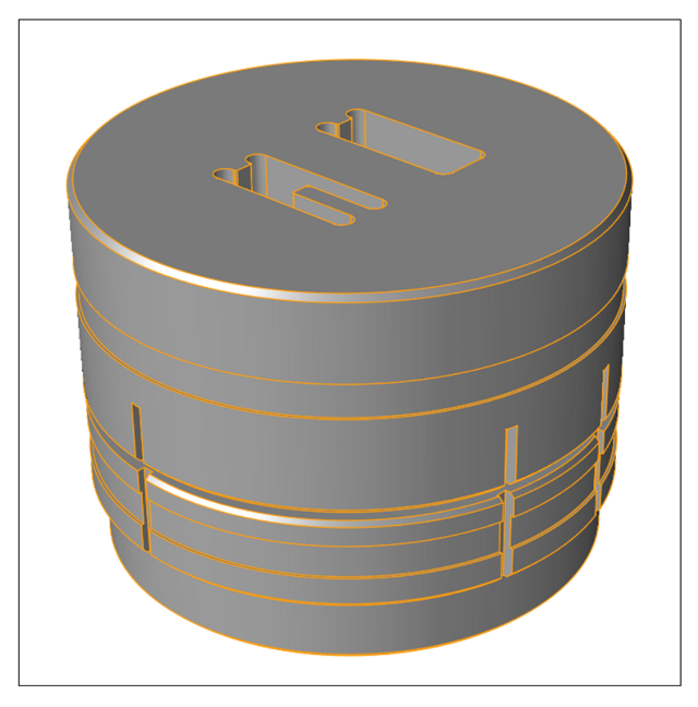
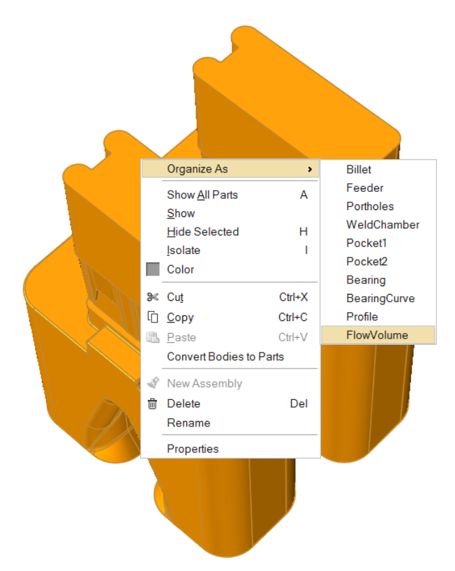
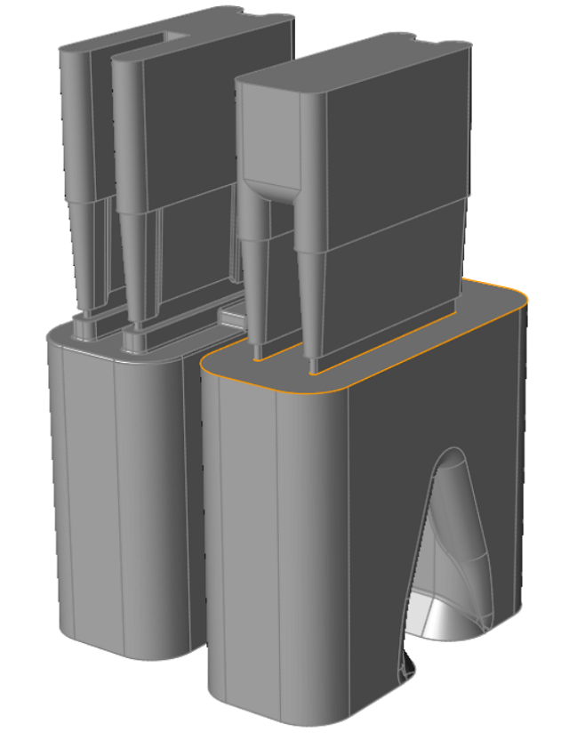
Combine Flow Volume
Hold CTRL and click on each flow solid as shown.
Right-click on either selected solid and click Organize As > FlowVolume.
The two separate Flow Volume pieces are now part of the same
FlowVolume piece.
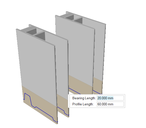
Extract Bearing Region
Zoom in to the region where bearing starts.
Click the Bearing icon.
Select the bearing start surface.
Program will automatically scan the geometry and discard the
relief region and create bearing and profile solids.
Note: Once the bearing is extracted,
you will be prompted to specify lengths for bearing and profile solids. You can keep
the default value and proceed. Profile region is 3 to 5 times the bearing
region.
Note: Profile is included in the model to capture how the profile
deflects.
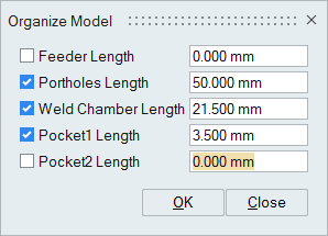
Organize Flow Volume
Click the Organize Volumes based on Length Icon.
A micro dialogue will pop up, where you must enter the following
measurements:
Press OK to close the window.
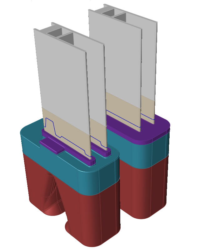
Inspire Extrude will cut the flow volume length
based on the component lengths specified and organize them into their respective
components automatically.
Create the Billet
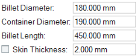
Click the Create Billet icon.
In the small window that pops up, specify the below billet dimensions and press
Enter.
Note: Leave the Skin thickness checkbox unchecked.
Press Esc to exit this panel.
The billet is created according to the specified dimensions.
The computation begins with an upset billet, thus the billet is created with upset
length based on container diameter.
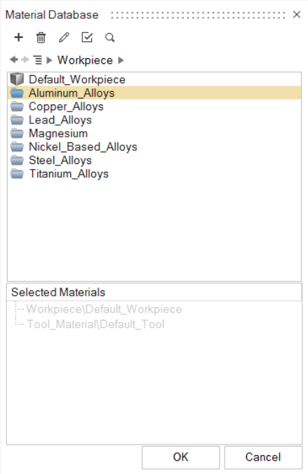
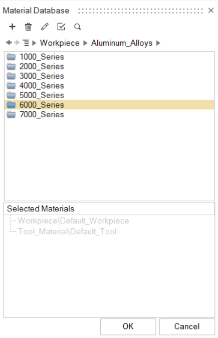
Select the Material
Click the Materials icon.
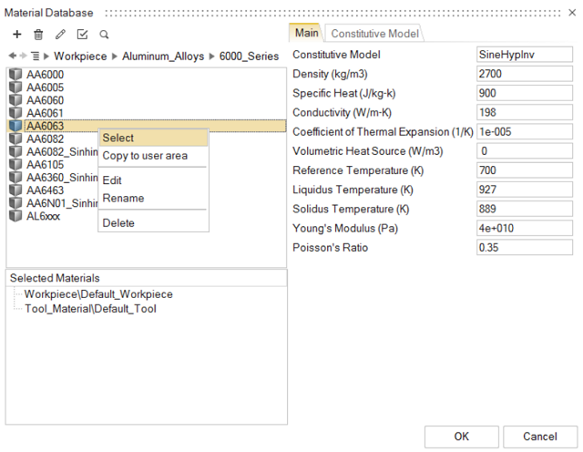
Drill down to the respective alloy Aluminum_Alloys > 6000_Series > AA6063
Right-click on the alloy name and click Select.
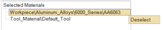
The chosen alloy is now added to the Selected
Materials window.
Note: To deselect a material in the
Selected Materials window, right-click and click
Deselect.
Click OK to close the Material
Database.
Click File > Save As to save the model at the desired location.
Note: It is recommended that you always save the model file in a newly created
folder to avoid conflict with older/existing model files.
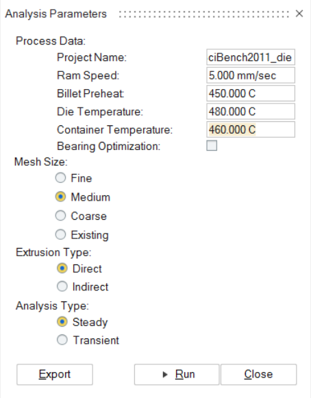
Specify Process Parameters and Simulate
Click theSubmit job for analysis icon to run the
simulation.
In the Analysis Parameters window that pops up, enter
values as shown.
Click the Run button.
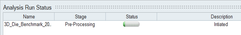
On successful launch of the run, you can monitor the status
of the simulation.
Status after submitting the job
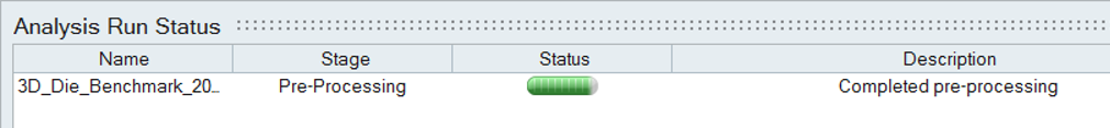
Status after meshing is completed
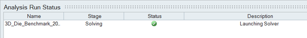
Status when job is running in the solver
View Simulation Results
Click the various Result Types to change the analysis
output. This data provides a detailed understanding of how material deforms and flows
during extrusion. Using this data, we can detect flow imbalances at the die exit.
Understanding the material flow in die regions such as portholes and pockets helps in
redesigning to improve the performance of the die.
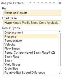
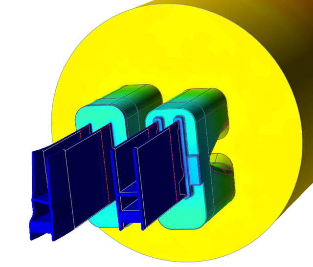
Select Pressure under Result
Types.
The pressure at the ram end provides the extrusion force required to push the
billet. This data also provides information on the resulting extrusion loads on
the die surfaces, and can be used to predict tool deflection.
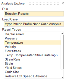
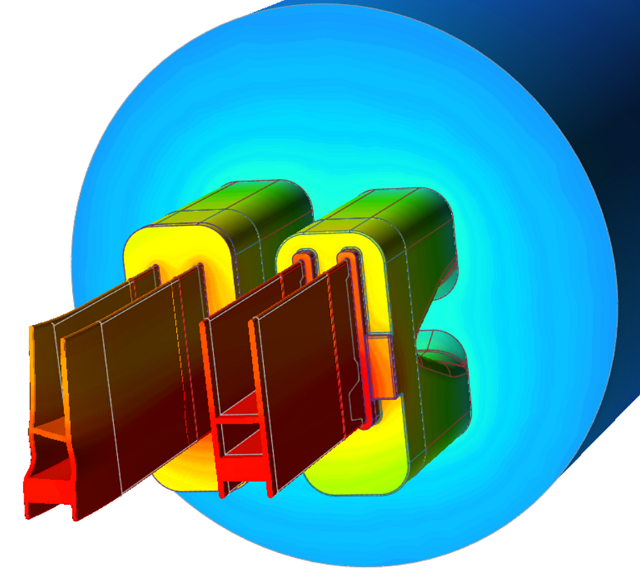
Select Temperature under Result
Types.
Understanding temperature distribution is the key to successful extrusion.
Flow stress of a material is a strong function of temperature and strain rate.
In addition, key material characteristics such as grain size depend on
temperature. Temperature data is used to determine where excessive heating
occurs in the die due to stress work. Temperature distribution in the profile
region is used to determine the surface quality and other material
characteristics.
In the case of hollow profiles, the solver
calculates seam weld location and strength.