Tutorial: Optimizing Topography
Tutorial Level: Beginner Defeature a model, run, and review the results of a topography optimization
- Run a baseline analysis of an oil pan to establish realistic design targets
- Use a defeatured model to set up and run a topography optimization
- Review the results of the topography optimization
Overview
Topography optimization is an advanced form of shape optimization that generates beads or swags on a design space. This approach is ideal for maximizing the stiffness of components without adding mass. It can also be used to maximize the frequency of a model, depending on your objective. Note that topography optimization only works on parts that are defined by surface geometry.
Typically, beads are very regular and are often simply aligned to major geometry features. Although they are well understood by manufacturers and do increase the stiffness of structures, topography optimization will usually result in a bead pattern that outperforms standard bead layouts.
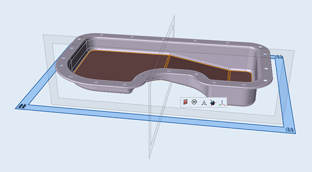
In this tutorial, you will run a baseline analysis and topography optimization on a typical oil pan design space.
Analyze a Baseline Model
Let's start by opening the model and running a baseline analysis. Performing analysis on a model before setting up optimization helps ensure that any constraints and other parameters are reasonable.
-
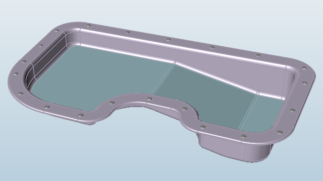
Double-click the baseline_oilpan.stmod file to load it in
the modeling window. Note that it has a pressure applied to the base part and is
restrained with fasteners at the bolt holes.
- Make sure the display units in the Unit System Selector are set to MPA (mm t N s).
-
On the Structure ribbon, click the Run OptiStruct
Analysis
 button in
the Analyze tool group to open the Run OptiStruct
Analysis window.
button in
the Analyze tool group to open the Run OptiStruct
Analysis window.

Tip: To find and open a tool, press Ctrl+F. For more information, see Find and Search for Tools. -
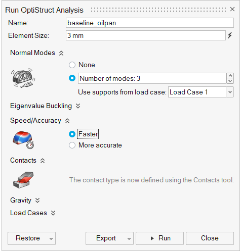
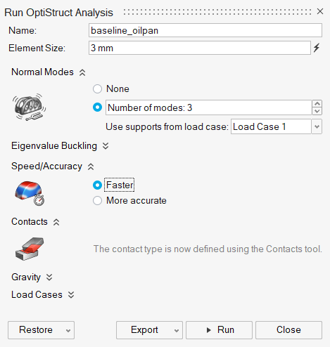
Run the analysis using the following settings:
- Change the Element Size to 3.0 mm.
- Set Speed/Accuracy to Faster.
- Select Load Case 1 in the Load Cases dropdown.
- Click Run to perform the analysis.
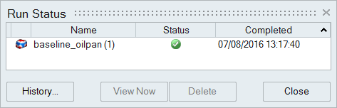
-
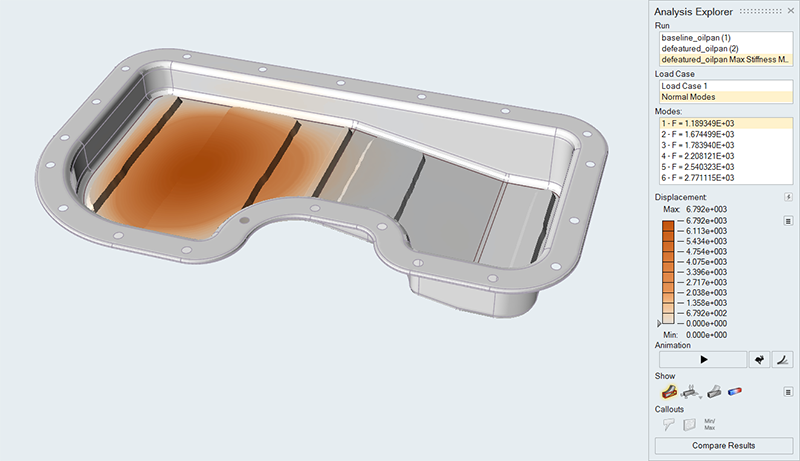
When the run is complete, select it in the Run Status window and click View
Now to see the results.
-
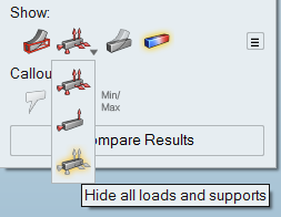
In the Analysis Explorer, click Show Selected Load Case
 and select
Hide all Loads and Supports
and select
Hide all Loads and Supports
 .
.
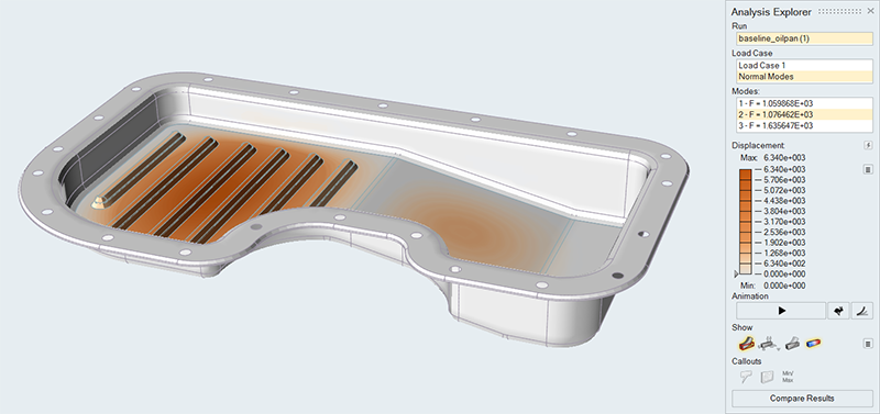
-
In the Analysis Explorer, select Normal Modes from the
Load Case dropdown and review the modes.
- Close the Analysis Explorer.
Prepare the Model for Topography Optimization
The best starting point for topography optimization is a design region without complex definition within the CAD. In many cases, the Holes tool can be used to remove existing beads and fill in holes.
-
On the Geometry ribbon, click the Simplify
 tool, and then click the Holes
 tool on the secondary ribbon.
Tip: To find and open a tool, press Ctrl+F. For more information, see Find and Search for Tools.
tool on the secondary ribbon.
Tip: To find and open a tool, press Ctrl+F. For more information, see Find and Search for Tools. -
Click the Reset
 button on the guide bar.
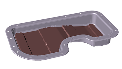
-
Zoom in on one of the beads and double-click one of the bottom fillets (nearest
the bottom of the oil pan).
This will chain select the entire bead.
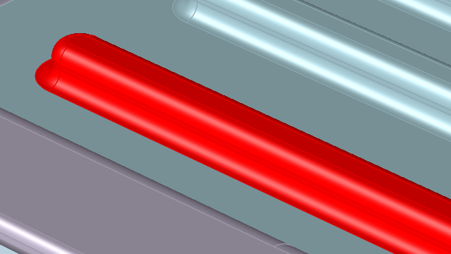
-
Click on one of the selected red faces to remove the entire bead.
-
Repeat the procedure to remove the remaining beads on the oil pan.
Tip: Alternatively, you can open the defeatured_oilpan.stmod file to load it in the modeling window. - Right-click and mouse through the check mark to exit, or double-right-click.
Rerun the Analysis and Compare Results
Now rerun the analysis with the same settings and compare the results with the baseline analysis from Step 1.
-
On the Structure ribbon, click the Run OptiStruct
Analysis
button in the
Analyze tool group to open the Run OptiStruct
Analysis window.
-
Run the analysis using the following settings:
- Change the Element Size to 3.0 mm.
- Under Normal Modes, select Number of modes: 3.
- Select Load Case 1 from the Use supports from load case dropdown.
- Make sure that Speed/Accuracy is set to Faster.
- Click Run to perform the analysis.
-
When the run is complete, select it in the Run Status window and click View
Now to see the results.

-
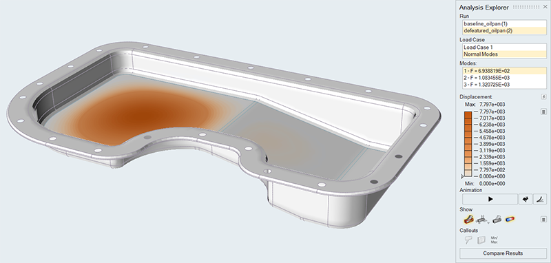
In the Analysis Explorer, select Normal Modes from the
Load Case dropdown and review the modes.
Note: The local mode shape where the beads were removed decreased from 1071 Hz to 693 Hz.
Run Topography Optimization
The next step is to define the design space and run a topography optimization.
-
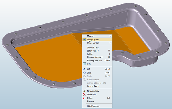
Right-click on the base part to open the context menu, and select
Design Space.
-
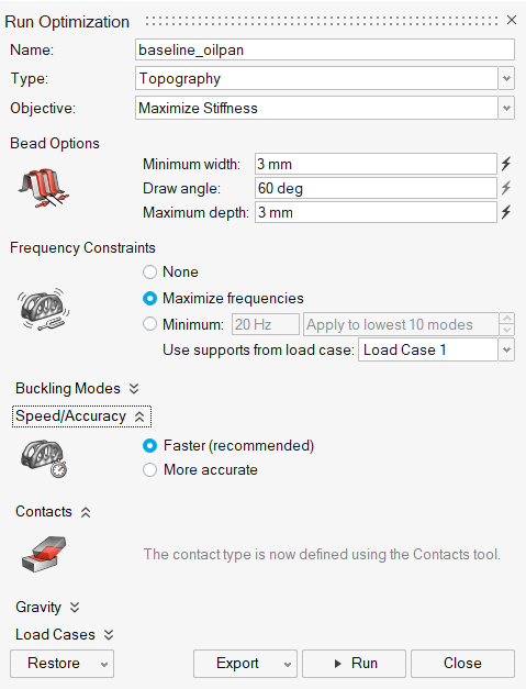
On the Structure ribbon, click the Run Optimization
button in the Optimize tool
group.

-
Run the optimization using the following settings:
-
When the run is complete, select it in the Run Status window and click View
Now to see the results.

-
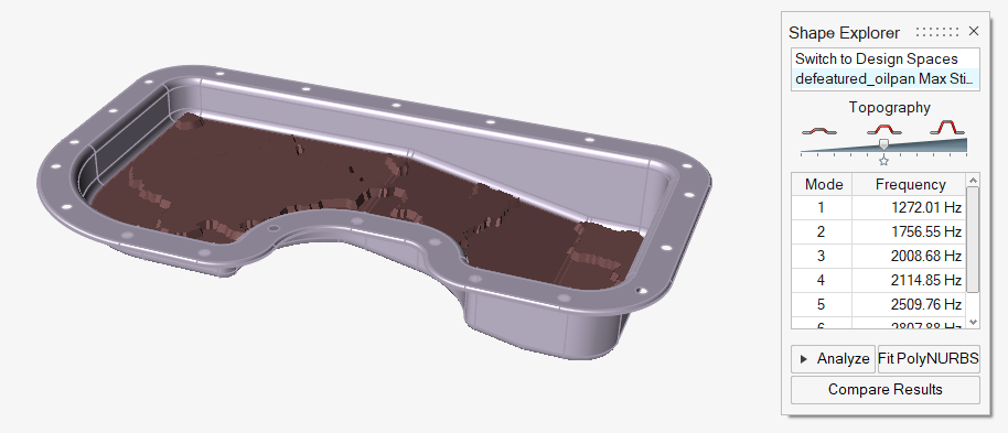
In the Shape Explorer, note that Mode 1 has increased to 1268 Hz with a lower
bead height than in the original part.
Note: Interpreting the results of topography optimization is often helped by performing multiple runs with different bead option parameters and bead patterns. This highlights key areas that benefit from the extra form and increased section modulus that typically result from topology optimization.
Apply Bead Patterns, Rerun, and Reanalyze the Model
Linear, circular, and radial bead patterns are sometimes desired for manufacturing or other reasons. These bead patterns can be applied using the Bead Pattern tool.
-
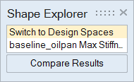
In the Shape Explorer, select Switch to Design
Spaces.
-
On the Structure ribbon, click the Bead Patterns
 tool,
and then click the Linear
tool,
and then click the Linear
 tool on the secondary ribbon.
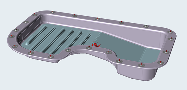
- Select the base of the oil pan.
-
Set the plane of symmetry as shown. Click the Rotate 90
Degrees
 button on the microdialog if needed to change the
direction of the beads.
button on the microdialog if needed to change the
direction of the beads.
- Right-click and mouse through the check mark to exit, or double-right-click.
-
On the Structure ribbon, click the Run Optimization
button in the
Optimize tool group.
-
Rerun the topography optimization with the same parameters as before:
Note: Note the linear alignment of the beads to the defined vector. Also note that Mode 1 is now 1165 Hz. This is better than the baseline result, but not as high as the initial optimization run.
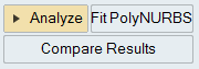
-
In the Shape Explorer, click the Analyze button to
analyze the generated shape.
-
When the run is complete, select it in the Run Status window and click View
Now to see the results.