
Tutorial: Grounded Fastener Optimization
Tutorial Level: Beginner Enable grounded fastener optimization to improve load distribution into the supports.
- Set up and run a baseline analysis of a hanger bracket to establish realistic design targets
- Create a defeatured model to set up and run a standard topology optimization
- Enable fastener optimization to improve load distribution into the supports
Overview: Fastener Load Optimization
Evenly distributing or limiting the maximum force in all bolts, screws, and other connections in a structure is a common aim of good design practice. When structures become complex in shape or loading, it can be difficult to achieve this objective. One approach is to use topology optimization to redistribute material away from direct load paths so that underutilized fasteners carry more of the applied load. Inspire provides the ability to constrain the load in a grounded screw or grounded bolt to achieve improved load distribution in a structure.
- In many structures, loads are not uniformly applied and geometry is often not symmetric. This can lead to large variations in the forces that the fasteners and connection points carry.
- Changing the topology of the structure will change the amount of load in each fastener.
- By limiting the maximum load in a fastener or set of fasteners, the topology generated by Inspire can more evenly distribute the resultant forces, reducing the maximum stresses and helping torque retention.
Set up the Hanger Model
-
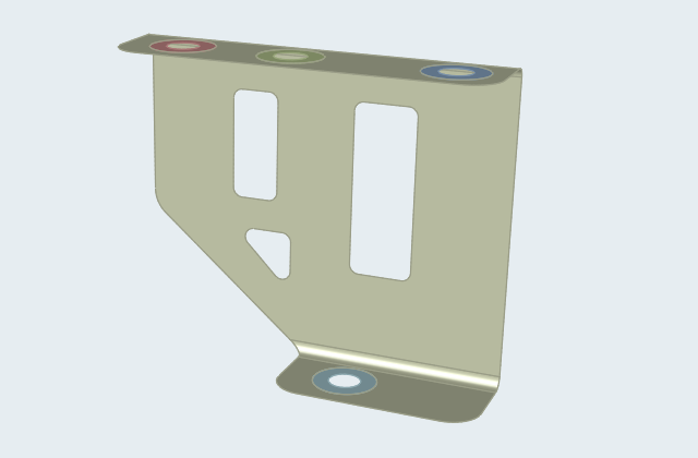
Double-click the hanger_geometry.stmod file to load it in
the modeling window. This is a surface model of a typical hanger bracket. Note
that all parts have a 4 mm thickness assigned, but there are no loads or
supports in the model.
- Make sure the display units in the Unit System Selector are set to MPA (mm t N s).
-
Select the Fasteners tool on the
Structure ribbon.
 Tip: To find and open a tool, press Ctrl+F. For more information, see Find and Search for Tools.
 -
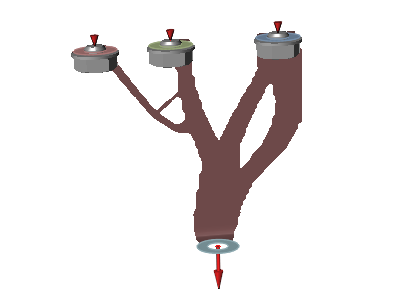
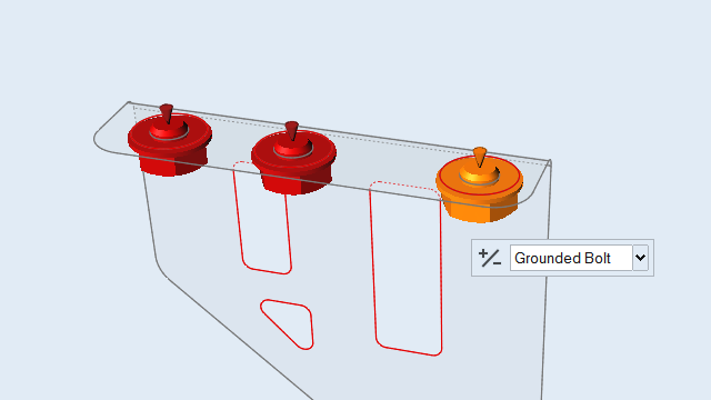
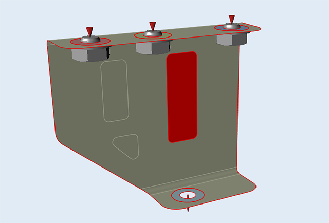
Select the Single Holes and Grounded
Bolt options on the guide bar.

- Choose the three edges on the bosses (B1, B2, and B3) and click Apply to add grounded bolts.
-
Select the bolts and use Reverse Direction (+/-) on the
microdialog to orient the grounded bolts as shown.
 Note: Note that using grounded bolts means there is no need to separately define supports on these fasteners.
 -
On the Structure ribbon,
click the Force
 button
in the Loads tool group.
button
in the Loads tool group.

-
Apply a force of 1000 N to part B4 in the Y direction as shown.
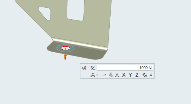
- Right-click and mouse through the check mark to exit, or double-right-click.
Run a Baseline Analysis
-
On the Structure ribbon, click the Run OptiStruct
Analysis
 button on the Analyze tool
group to open the Run OptiStruct Analysis window.
button on the Analyze tool
group to open the Run OptiStruct Analysis window.

-
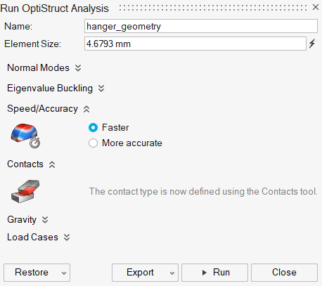
Run the analysis using the following settings:
- Change the Element Size to 3.309 mm.
- Set Speed/Accuracy to Faster.
- Click Run to perform the analysis.
-
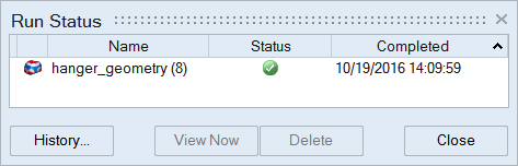
When the run is complete, double-click the name of the run to view the
results.
-
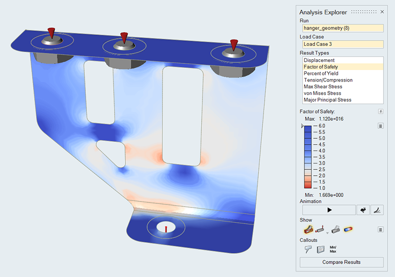
In the Analysis Explorer, examine the results and note that the minimum factor
of safety is 1.6.
- Switch to the Displacement result type.
-
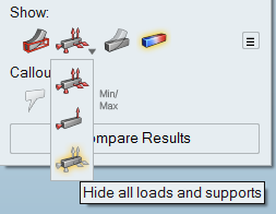
Select Hide All Loads and Supports under the
Show icons.
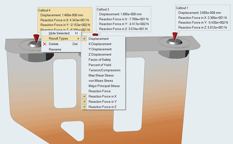
- Create a callout at the center of each grounded fastener hole.
-
Right-click each callout, select Result Types from the
context menu, and verify Reaction Forces in X,
Y, and Z are selected.
-
Select Show All Loads and Supports under the
Show icons.
Note that the Z coordinate is along the axis of each hole.
- Right-click and mouse through the check mark to exit, or double-right-click.
Prepare the Model for Topology Optimization
The best starting point for topology optimization is a design region without any predefined cutouts. In many cases, the Patch tool can be used to fill holes in surface models.
- Open the hanger_run.stmod file or continue with your model from the previous step.
-
On the Geometry ribbon, select the
Patch tool.

-
In the Patch guide panel, click the Edges collector to
select the edge of each cutout, and then click Apply to
remove it from the bracket.
- Right-click and mouse through the check mark to exit, or double-right-click.
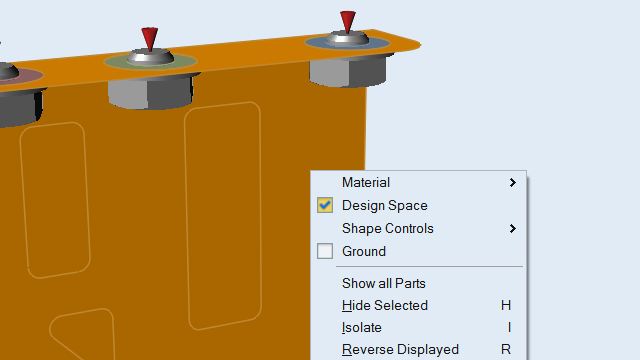
-
Right-click the bracket and designate it as the design space.
Run a Topology Optimization
-
On the Structure ribbon, click the Run Optimization
button on the Optimize tool
group to open the Run Optimization window.

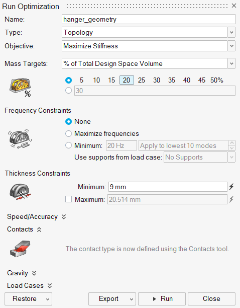
-
Run the optimization using the following settings:
- Select Topology for the optimization Type.
- Select Maximize Stiffness for the optimization Objective.
- Under Mass Targets, select % of Total Design Space Volume from the dropdown menu and choose 20 percent.
- Under Frequency Constraints, select None.
- Under Thickness Constraints, increase the Minimum to 9 mm.
- Click Run to perform the optimization.
-
When the run is complete, double-click the name of the run to view the
results.

-
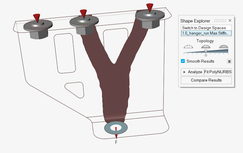
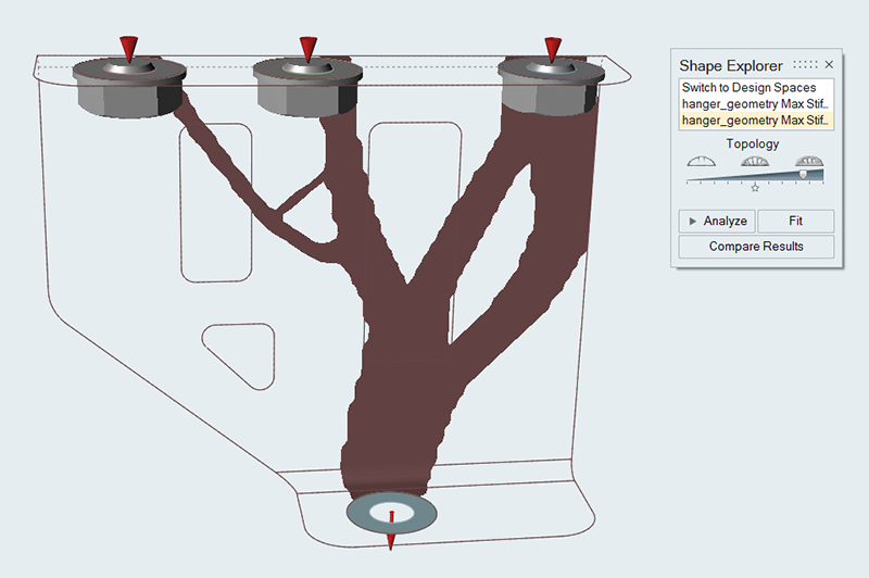
In the Shape Explorer, examine the results.
Note how the optimization distributes the material for most direct attachments to ground.
-
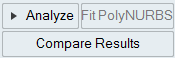
Click the Analyze button on the Shape Explorer to run a
reanalysis.
-
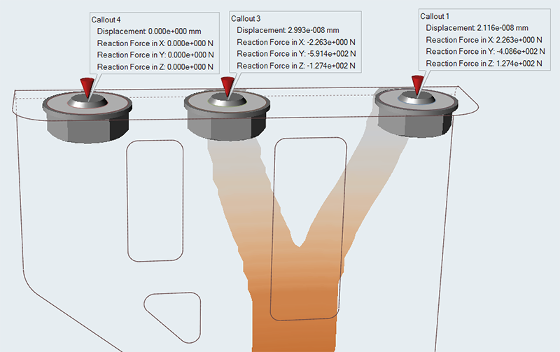
After loading the results, the callouts that were defined earlier should still
be active. Note how the reaction force in the Z direction for the center and
rightmost bolt have changed.
Define Maximum Bolt Loads
- Open the Hanger_opti_run.stmod file or continue with your model from the previous step.
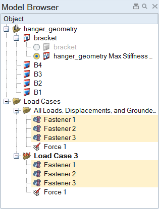
-
Hold Ctrl and select the three grounded bolts in the
Model Browser.
-
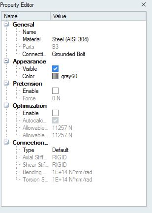
Open the Property Editor (F3) and select the Enable
option under Optimization.
-
Deselect the Autocalculate Allowable Forces
option.
Inspire defaults to Autocalculate Allowable Forces. This value is based on the yield stress of the fastener material and the fastener cross section.
- Enter 444 N for Allowable Axial Force and the Allowable Shear Force. The goal is to get more even force distribution in the grounded fasteners.
Repeat the Topology Optimization
-
On the Structure ribbon, click the Run Optimization
button on the Optimize tool
group to open the Run Optimization window.
-
Repeat the optimization using the same settings as before.
-
Load and examine the results. Adjust the Topology slider
so that all the parts are connected. Note how the optimization now distributes
the material to all three grounded bolts.
-
Click the Analyze button on the Shape Explorer to run a
reanalysis.
- After loading the results, the callouts that were defined earlier should still be active. Note that all of the bolts now carry some load, and the maximum on the center bolt is below the defined maximum of 444 N. Your specific results will vary based on where you positioned the Topology slider before running the reanalysis.