
Run an SLM Analysis
Run an SLM additive manufacturing analysis for the selected print parts.
-
Click the
 button on the Analyze
icon.
button on the Analyze
icon.
 Tip: To find and open a tool, press Ctrl+F. For more information, see Find and Search for Tools.
 - Specify the process parameters.
-
Click Run to begin the analysis.
The run may take several minutes to several hours to complete, depending on the complexity of the model and the size of the mesh elements. If the run is completed successfully, a green flag will appear over the Analyze icon. If unsuccessful, a red flag will appear instead.
- Click the green flag or double-click the run name in the Run Status window to view the results.
Tip:
- Click
 on the Analyze icon to view the run status.
Runs that are being processed or that have not been viewed are shown in the
Run Status table.
on the Analyze icon to view the run status.
Runs that are being processed or that have not been viewed are shown in the
Run Status table. - Click
 on the Analyze icon to view the run history.
Runs that have been viewed previously are shown in the Run
History table.
on the Analyze icon to view the run history.
Runs that have been viewed previously are shown in the Run
History table. - The
 icon indicates that the run was
incomplete. Some but not all of the result types may be available. You
should run a new analysis to generate complete results.
icon indicates that the run was
incomplete. Some but not all of the result types may be available. You
should run a new analysis to generate complete results. - To view multiple runs, hold the Ctrl key while selecting runs, then click the View Now button. If several runs are associated with the same part, the result from the most recently completed run for that part will be activated in the modeling window.
- To open the directory where a run is stored, right-click the run name and select Open Run Folder.
Process Parameters
Process parameters impact what result types are available at the end of the simulation, as well as the processing time and accuracy of results.
Inherent Strain
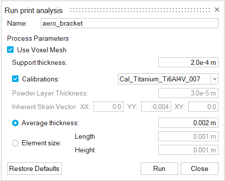
- Analysis Type
- The analysis type determines what result types will be available at the end of the simulation. Selecting Inherent Strain will generate results for displacement, Von Mises stress, collision distance, layer shifting, and failure index.
- Use Voxel Mesh
- Enable this option to use a voxel mesh instead of a tetrahedral mesh for a faster analysis with a less detailed result.
- Support thickness
- The thickness of a printed support's outer shell. The number will depend on the printer being used.
- Activation layer thickness
- The height which the solver simulates in each step. Usually, the real powder thickness is very
small. You can define this parameter as the actual thickness of a single
powder layer for accuracy, or choose a larger value (up to 20 times the
single layer's thickness) to simulate more than one layer at once and reduce
simulation time. Note: This field is not available when Use Voxel Mesh is enabled.
- Calibrations
- Enable this option to select available calibrations from the dropdown menu.
- Powder layer thickness
- For powder-based 3D printing processes, this indicates the thickness of the powder layer that is spread across the printing bed. This information is unique to the printer model and should be available from your 3D printer.
- Inherent Strain Vector
- This represents a symmetric tensor written in vector form, with components
[XX, YY, XY]. The values in these fields represent the material's shrinkage
in all directions as it cools. Note: These parameters are only available for Inherent Strain analyses in which the Calibrations option is not selected.
- Average thickness
- The simulation's results are shown as a tetrahedral mesh by default, or a voxel mesh if Use Voxel Mesh is enabled. You can enter either an average thickness or an element size for the mesh.
- Element size
- If you choose to define the mesh in terms of element size, enter a length and height. A good starting point is generally 1 x 1 mm. Reducing the element size improves accuracy, but increases the time of the analysis.
- Support element size
- Change the element size for voxelized supports.
Thermal Coarse
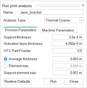
- Analysis Type
- The analysis type determines what result types will be available at the end of the simulation. Selecting Thermal Coarse will generate results for temperature.
- Support thickness
- The thickness of a printed support's outer shell. The number will depend on the printer being used.
- Activation layer thickness
- The height which the solver simulates in each step. Usually, the real powder thickness is very small. You can define this parameter as the actual thickness of a single powder layer for accuracy, or choose a larger value (up to 20 times the single layer's thickness) to simulate more than one layer at once and reduce simulation time.
- HTC Part-Powder
- The heat transfer coefficient between the print part and the powder.
- Average thickness
- The simulation's results are shown as a tetrahedral mesh. You can enter either an average thickness or an element size for the mesh.
- Element size
- If you choose to define the mesh in terms of element size, enter a length and height. A good starting point is generally 1 x 1 mm. Reducing the element size improves accuracy, but increases the time of the analysis.
- Support element size
- Change the element size for voxelized supports.
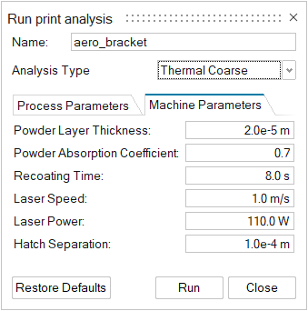
- Powder layer thickness
- For powder-based 3D printing processes, this indicates the thickness of the powder layer that is spread across the printing bed. This information is unique to the printer model and should be available from your 3D printer.
- Powder Absorption Coefficient
- The Powder Absorption Coefficient accounts for the fact that the powder absorbs some of the laser's energy. For example, if you set this field to 0.7 it means that 70% of the laser's energy is used to heat the print part.
- Recoating Time
- The time it takes for the printer's recoater to place a new layer of powder on the part. The number will depend on the printer being used.
- Laser Speed
- The speed of the laser as it passes over the powder layer. The number will depend on the printer being used.
- Laser Power
- The power of the printer's laser. The number will depend on the printer being used.
- Hatch Separation
- The distance between the center lines of the laser beam passes. The number will depend on the printer being used.