Optimize Orientation: Optimize the orientation of the print
part to minimize print time, supports, and/or deformation.
Max Build Height: Maximize the build height for efficient
printing and cooling.
Min Build Height: Minimize the build height to achieve the
shortest printing time.
Surface: Orient the print part in relation to a surface on
the part.
Optimize Orientation
Optimize the orientation of the print part to minimize print time, supports, and/or
deformation. You can also orient the part based on a weighted average of all three
factors.
The part which was previously selected for printing is displayed in red
and the Orientation Optimization window and
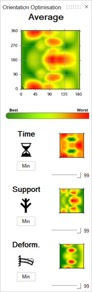
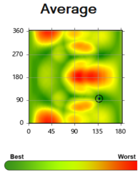
Orientation table open.The Average heatmap shows optimal orientations for
the print part based on weighted averages of fastest print time, fewest supports
needed, and least amount of part deformation. The Time,
Support, and Deform heatmaps
show optimal orientations for each factor, respectively.
Optimize the print part orientation using one of the following methods:
Click one of the Min buttons to orient the part
for optimal print time, support, or deformation.
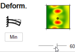
Use the slider bars to give higher or lower priority to each factor in
the Average heatmap. For example, if deformation is
most important, support is slightly less important, and time is not
important at all, you would set the Deform. slider to
100, the Support slider to 90, and the
Time slider to 0. The
Average heatmap will change based on the
priorities you assign to each factor.
Click a point on one of the heatmaps to view possible orientations in
the modeling window.
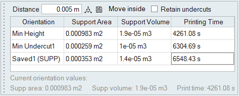
Enter a Distance in the Orientation table to configure
the distance between the part and printing bed. The minimum distance is
0.002 m.
Optional: In the Orientation table, click the Save icon
to save the orientation.
Right-click and mouse through the check mark to exit, or double-right-click.
Maximize or Minimize Build Height
Maximize the build height for efficient printing and cooling, or minimize the build
height to achieve the shortest printing time.
Click the Max Build Height icon to maximize the build height for efficient
printing and cooling. This orientation protects the part from cooling
deformations, ensuring that the part prints according to design and build
dimensions.
Click the Min Build Height icon to minimize the build height to achieve
the shortest printing time.
Enter a Distance in the Orientation table to configure
the distance between the part and printing bed. The minimum distance is
0.002 m.
Optional: In the Orientation table, click the Save icon
to save the orientation.
Right-click and mouse through the check mark to exit, or double-right-click.
Orient the Print Part to a Surface
Orient the print part in relation to a surface on the part.
Click the Surface icon and then select a surface on the part. The
selected surface will be rotated to face the printing bed with its normal
oriented toward gravity.
Enter a Distance in the Orientation table to configure
the distance between the part and printing bed. The minimum distance is
0.002 m.
Optional: In the Orientation table, click the Save icon
to save the orientation.
Right-click and mouse through the check mark to exit, or double-right-click.
Save an Orientation
Use the Orientation table to save the orientation of the print part.
The Orientation table is displayed next to the printer bed,
Use one of the Orientation tools to orient the print part.
Click the Save icon on the Orientation table to save the orientation.
Tip:
For surfaces on the part with angles of less than 45 degrees, support is
required. These areas are shown in yellow and update automatically as the
part is rotated using the Move tool.
If the part accidentally extends outside of the printing bed, select the
Move Inside option on the Orientation table to
place it inside of the printing bed.
By default, undercuts are only shown in yellow when the Orientation tool is
active. Enabling the Retain Undercuts option on the
Orientation table makes the undercuts visible when using other tools. This
is useful when you are modifying the geometry and want to see how the
undercuts change as a result.
If you rotate the part or create new orientations, the Current
orientation values at the bottom of the table update
automatically. Select a row in the Orientation table to restore that
orientation.

 icon.
Tip: To find and open a tool, press Ctrl+F. For more information, see Find and Search for Tools.The part which was previously selected for printing is displayed in red and the Orientation Optimization window and Orientation table open.
icon.
Tip: To find and open a tool, press Ctrl+F. For more information, see Find and Search for Tools.The part which was previously selected for printing is displayed in red and the Orientation Optimization window and Orientation table open.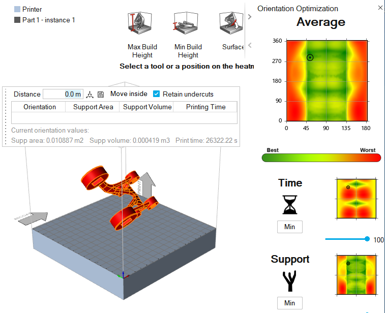
 to save the orientation.
 icon to maximize the build height for efficient
printing and cooling. This orientation protects the part from cooling
deformations, ensuring that the part prints according to design and build
dimensions.
icon to maximize the build height for efficient
printing and cooling. This orientation protects the part from cooling
deformations, ensuring that the part prints according to design and build
dimensions. icon to minimize the build height to achieve
the shortest printing time.
icon to minimize the build height to achieve
the shortest printing time. icon and then select a surface on the part. The
selected surface will be rotated to face the printing bed with its normal
oriented toward gravity.
icon and then select a surface on the part. The
selected surface will be rotated to face the printing bed with its normal
oriented toward gravity.
 tool.
tool.