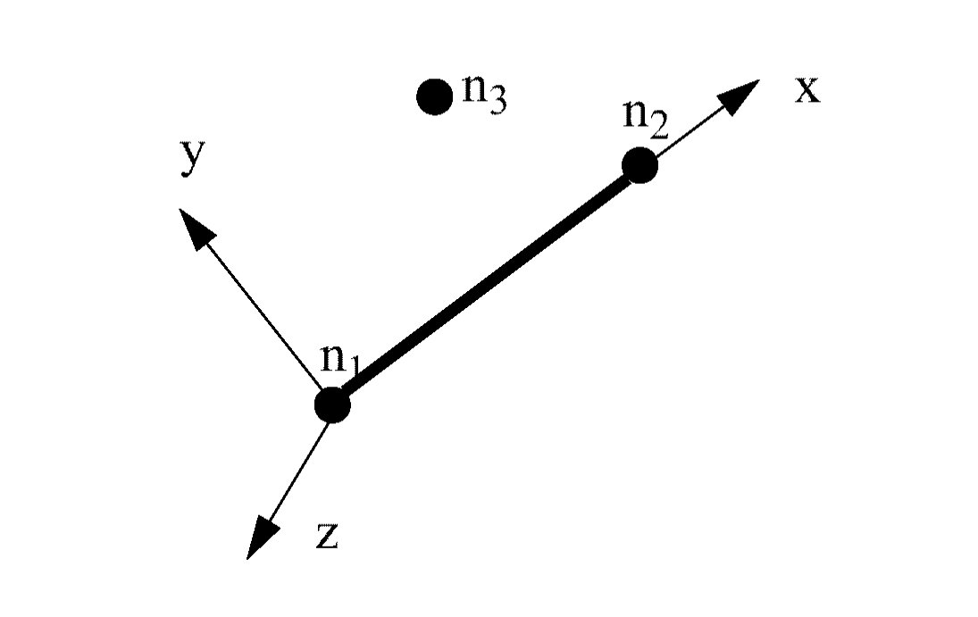
Beam type spring elements are best defined using three nodes (Figure 1). Nodes 1 and 2 are the two ends of the element and define
the local X axis. Node 3 allows the local Y and Z axes to be defined. However, this node
does not need to be supplied.
If all three nodes are defined, the local reference frame is calculated by:
If node 3 is not defined, the local skew frame that can be specified for the element is
used to define the Z axis. The X and Y axes are defined in the same manner as
before.
If no skew frame and no third node are defined, the global Y axis is used to replace the Y
skew axis. If the Y skew axis is collinear with the local X axis, the local Y and Z axes are
placed in a totally arbitrary position. The local Y axis is defined at time zero, and is
corrected at each cycle, taking into account the mean X axis rotation.Figure 1. Element Definition