
OS-V: 0260 Shell Bending under a Tip Load
A beam is analyzed for bending due to tip load. OptiStruct investigates the vertical steady-state displacement at the tip of the beam.
Model Files
Benchmark Model
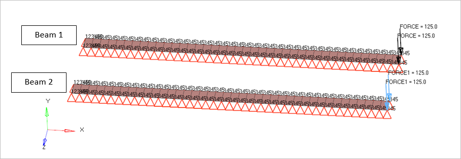
Two beams are analyzed, Beam1 without follower load and Beam2 with follower load. Shell elements are used to model the beams which is 400 mm long consists of 40 elements and a cross section of 20 mm. All the nodes are constrained for the 3,4 and 5 degrees of freedom and the ends of the beams are constrained in all degrees of freedom. Both the beams are loaded at the edge by a point force of 125 N on each node in the negative y direction. The load on the Beam1 is not having a follower force whereas the load on the Beam2 is a follower force. Nonlinear static analysis is performed with Large displacement.
- Material Properties
- Value
- Young's Modulus
- 1000 MPa
- Poisson's Ratio
- 0.0
- Density
- 10000 kg/m3
Nonlinear Static Analysis Results
| Non-Follower Load | y-Displacement (mm) |
Follower Load | y-Displacement (mm) |
|---|---|---|---|
| Bisshopp and Drucker | 240 | Bisshopp and Drucker | 291 |
| CBEAM | 242 | CBEAM | 277 |
| Normalized | 0.99173554 | Normalized | 1.05054152 |
Reference
Bisshopp, K. E., and D. C. Drucker, “Large Deflections of Cantilever Beams,” Quarterly of Applied Mathematics, vol. 3 272, 1945