This benchmark illustrates the structural response of a power law creeping material
in a geometrical configuration subjected to pure torsion. OptiStruct examines strain at the edge of the shaft.
The model examines the torsional creep in circular shaft with 2 variations:
Relaxation at constant twist
Forward creep at steady twist rate
Relaxation at Constant Twist
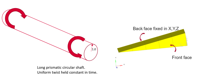
Twist is applied to the shaft and remains constant from 0 to 100 s. Total strain and
creep strains then analyzed.Figure 1. Model and Loading Description
Model Files
Before you begin, copy the file(s) used in this problem
to your working directory.
Four 20-noded brick elements, plus one 16-noded wedge are used. All nodes on lower
face are fixed in X, Y, Z.
X, Y displacements given at all nodes of front face using cylindrical
system: 0.002 mm
Rotation is given at mid-side nodes: 0.001 radians
Uniform twist of 0.01 radians/unit length is held constant in time from 0 to 100
s.
Twist is instantaneously applied to the shaft and then maintained constant. The
initial response is elastic and subsequently the structure response with a
progressive accumulation of creep strain. Stress reduces (relaxes) slowly till 100 s
due to creep.
Material Properties
Value
Young's modulus
10 GPa
Poisson's ratio
0.3
Creep law equation
Where,
Equivalent creep strain rate
Equivalent stress (Mises)
Nonlinear Static Analysis Results
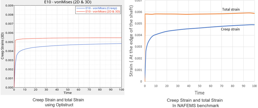
An implicit visco-elastic solution method was used. Displacement, total strain and
creep strain results are analyzed at the edge of the shaft at 100 s.
OptiStruct
NAFEMS
Normalized Target Value
Total Strain (*10-3)
5.46
5.77
0.95
Creep Strain (*10-3)
4.85
4.77
1.01
Comparison of strain plots.Figure 2. Comparison of Total Strain and Creep Strain at the Edge of
the Shaft
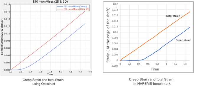
Forward Creep at Steady Twist Rate
A steadily increasing twist is applied at constant rate to the shaft.
The stresses increase from zero to steady value. The loads, which cause this
steady-state behavior are referred as “primary” loads.
This model is the same as used in Relaxation at Constant Twist; except the boundary
conditions.Figure 3. Model and Loading Description
Model Files
Before you begin, copy the file(s) used in this problem
to your working directory.