OS-T: 4090 Manufacturing Constraints of a Composite Structure
In this tutorial you will perform a free-size optimization with manufacturing constraints.
One of the advantages with composite materials is that the structural performance can be controlled precisely by choosing the appropriate ply thickness, ply orientation, stacking sequence, ply materials, and so on. The ability to vary many different parameters provides greater flexibility, but at the same time it is tougher to optimize the part as the number of design variables increases many fold. OptiStruct has the ability to directly or indirectly optimize the ply thickness, ply orientation and stacking sequence for composite structures.
Free-size optimization handles the thickness of each ply in each element as a design variable and optimizes the structure by determining the optimal thickness distribution for each ply in the laminate.
For several reasons, every composite manufacturer has their own manufacturability standards for the laminated composites. These additional manufacturing constraints are to be included with free-size optimization to achieve an acceptable manufacturing solution. OptiStruct supports different manufacturability constraints that can be defined with free-size optimization. This tutorial helps explain the procedure used to define the manufacturing constraints in the free-size optimization of composite structures.
- Objective
- Minimize the Mass.
- Constraints
- Displacement of selected 6 nodes < 3 mm.
- Design Variables
- Thickness of each ply of each element in the design space.
Launch HyperMesh and Set the OptiStruct User Profile
-
Launch HyperMesh.
The User Profile dialog opens.
-
Select OptiStruct and click
OK.
This loads the user profile. It includes the appropriate template, macro menu, and import reader, paring down the functionality of HyperMesh to what is relevant for generating models for OptiStruct.
Open the Model
- Click .
- Select the Composite_Wing.hm file you saved to your working directory.
-
Click Open.
The Composite_Wing.hm database is loaded into the current HyperMesh session, replacing any existing data.
Review the Model Setup
In this step you will use HyperLaminate to define, review, and edit ply lay-up information.
The model is already set up for the analysis. The model properties, loads, boundary conditions, and loadsteps are already defined. The model has 15 components out of which the TopSkin and BottomSkin components are defined with the composite property PCOMP. The rest of the components are defined with PSHELL property which references the material property, Aluminum.
-
From the 2D page, click the HyperLaminate panel.
HyperLaminate opens.
-
In the Laminate Browser, Laminates section, click
TopSkin.
The TopSkin component properties display in the Laminate definition and Review sections. The Laminate definition section shows the ply material, ply thickness, ply orientation, and so on, which is shown graphically under the Review section.
- From the menu bar, click to exit HyperLaminate and return to HyperMesh.
Set Up the Optimization
Create Design Variable
- From the Analysis page, click the optimization panel.
- Click the free size panel.
- Select the create subpanel.
- In the desvar= field, enter Skins.
- Set type: to PCOMP(G).
- Using the props selector, select the TopSkin and BottomSkin properties.
- Clicks create.
Add a Minimum Dimension Manufacturing Constraints
- Select the parameters subpanel.
- Click desvars= and select Skins.
- Toggle minmemboff to mindim =, and enter 5.0.
- Click update.
Add Minimum Thickness Manufacturing Constraints
- Minimum laminate thickness of 0.2.
- A Minimum of 10% and a maximum of 60% thickness (of total laminate thickness) constraints defined for all the plies. This means that for each element, none of the plies will have thickness less than 10% or greater than 60% of the totals laminate thickness.
- The thickness of ply with ply angle of 45 degree to be same as the thickness of ply with ply angle of -45 degree.
- Select the composites subpanel.
- Click desvars= and select Skins.
- Under laminate thickness, toggle minimum thickness off to minimum thickness = and enter 0.2.
-
Click update.
The above defined minimum laminate thickness constraint is updated to the free-size design variable.
- Click edit.
- In the Card Image dialog, select PLYPCT.
- Under PLYPCT, select BYSET.
-
In the DSIZE_NUMBER_OF_PLYPCT= field, enter
4.
This specifies that ply percentage constraints will be defined on 4 plies. In the Card Image dialog, four additional lines appear, in which you can enter the ply percentage constraints.
- PANGLE
- Ply orientation to which the PLYPCT constraints are applied.
- PPMIN
- Minimum ply percentage thickness for the PLYPCT constraint.
- PPMAX
- Maximum ply percentage thickness for the PLYPCT constraint.
- PTMAN
- Manufacturable ply thickness.
Figure 3. 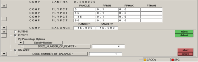
-
In the first COMP PLYPCT row, edit the constraints.
This defines that for each element, the thickness of the ply with ply angle 0, should be no less than 10% or more than 60% of the total thickness.
-
In the second COMP PLYPCT row, edit the constraints.
- For PANGLE, enter 45.
- For PPMIN, enter 0.1.
- For PPMAX, enter 0.6.
- Leave the PTMAN field blank.
-
In the third COMP PLYPCT row, edit the constraints.
- For PANGLE, enter -45.
- For PPMIN, enter 0.1.
- For PPMAX, enter 0.6.
- Leave the PTMAN field blank.
-
In the second COMP PLYPCT row, edit the constraints.
- For PANGLE, enter 90.
- For PPMIN, enter 0.1.
- For PPMAX, enter 0.6.
- Leave the PTMAN field blank.
-
Select BALANCE.
The BALANCE constraint ensures that two plies will always be of equal thickness.
- BALANCE
- BALANCE flag indicating that a balancing constraint is applied.
- BANGLE1
- First ply orientation to which the BALANCE constraint is applied.
- BANGLE2
- Second ply orientation to which the BALANCE constraint is applied.
-
In the BALANCE row, edit the constraints.
- For BANGLE1, enter 45.
- For BANGLE2, enter -45.
This defines that the plies with ply angle of 45 and -45 will always have the same thickness. - Click return to return from the panel.
- Click update to update the above defined manufacturing constraints to the free-size design variable.
- Click return to return from the free size panel.
Create Optimization Responses
- From the Analysis page, click optimization.
- Click Responses.
-
Create the mass response, which is defined for the total volume of the
model.
- In the responses= field, enter mass.
- Below response type, select mass.
- Set regional selection to total and no regionid.
- Click create.
-
Create the displacement response.
- Click return to go back to the Optimization panel.
Create Design Constraints
- Click the dconstraints panel.
- In the constraint= field, enter disp_constr.
- Click response = and select disp.
- Check the box next to upper bound, then enter 2.0.
- Using the loadsteps selector, select Subcase1 and Subcase2.
- Click create.
- Click return to go back to the Optimization panel.
Define the Objective Function
- Click the objective panel.
- Verify that min is selected.
- Click response and select mass.
- Click create.
- Click return twice to exit the Optimization panel.
Run the Optimization
- From the Analysis page, click OptiStruct.
- Click save as.
-
In the Save As dialog, specify location to write the
OptiStruct model file and enter
Wing_FreeSize_with_PLYPCT for filename.
For OptiStruct input decks, .fem is the recommended extension.
-
Click Save.
The input file field displays the filename and location specified in the Save As dialog.
- Set the export options toggle to all.
- Set the run options toggle to optimization.
- Set the memory options toggle to memory default.
-
Click OptiStruct to run the optimization.
The following message appears in the window at the completion of the job:
OPTIMIZATION HAS CONVERGED.
FEASIBLE DESIGN (ALL CONSTRAINTS SATISFIED).
OptiStruct also reports error messages if any exist. The file Wing_FreeSize_with_PLYPCT.out can be opened in a text editor to find details regarding any errors. This file is written to the same directory as the .fem file. - Click Close.
View the Results
OptiStruct provides element thickness, ply thickness information for all iterations, and also writes out displacement and von Mises stress results for the linear static analysis. This section describes how to view the results in HyperView.
View a Contour Plot of Element and Ply Thicknesses
-
From the OptiStruct panel, click HyperView.
HyperView launches within the HyperMesh Desktop and loads all .h3d result files.
-
On the Results toolbar, click
 to open the Contour panel.
- Set the Result type to Element thicknesses and Thickness.
-
Click Apply.
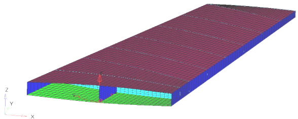
The contour of total laminate thickness for the selected iteration displays.
-
In the Results Browser, select the last design iteration
result.
Figure 4. 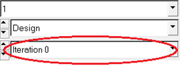
The contoured thickness is the optimal laminate thickness distribution for the current design.
View a Contour Plot of Ply Thickenesses
-
On the Results toolbar, click
 to open the Iso panel.
-
Click Apply.
The isometric view of the model displays.
-
In the Results Browser, click
 to activate the Component view.
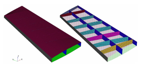
Figure 5. 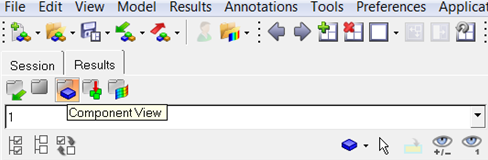
-
From the view controls in the Results Browser, click
 (Isolate Shown) and click the BottomSkin and
TopSkin components.
The two components are isolated.
(Isolate Shown) and click the BottomSkin and
TopSkin components.
The two components are isolated. -
On the Visualization toolbar, click
 to open the Exploded View panel.
- Click Add to add a new explosion view.
- Click one of the components to select it for translating.
- Under Translate, set the Direction to X Axis.
- In the Distance field, enter 5.
-
Click + to move the selected component in the positive X
direction. Repeat until the component is moved enough to view both the
components.
Figure 6. Laminate Optimized Thickness Contour 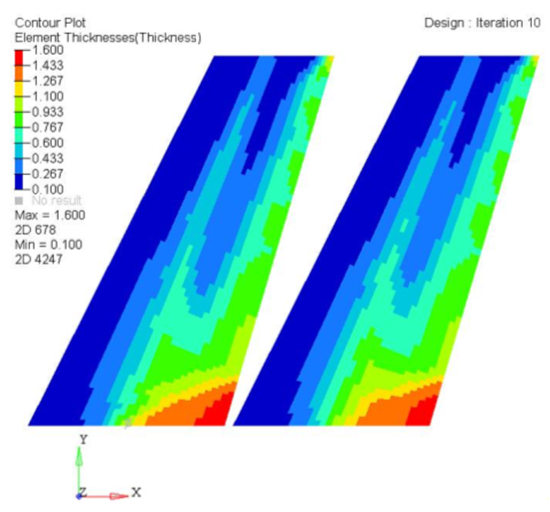
-
On the Results toolbar, click
to open the Contour panel.
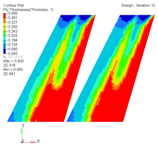
- Set the Result type to Ply Thickness and Thickness.
- Set Entity with Layer to 1.
-
Click Apply.
The first ply thickness contour displays. You can repeat these steps to plot the thickness for Ply 2, Ply 3, and Ply 4 or Max, and so on.
Figure 7. First Ply Optimized Thickness Contour