Select the oht_opti_ph3.fem file you saved
to your working directory.
Click Open.
Click Import, then click Close to
close the Import tab.
Set Up the Model
Import Final Optimization Properties
In the Import Browser, File field, browser for the
oht_opti_ph3.prop file.
Under Import options, select FE
overwrite.
Click Import.
The properties of the model are updated with the optimized
parameters.
Edit the Contol Cards
In the Model Browser, expand the Cards folder.
Delete the OMIT card.
Right-click on OMIT and select
Delete from the context menu.
HyperMesh asks you to confirm the delete.
Click Yes to continue.
Edit the OUTPUT card.
Click the OUTPUT card.
In the Entity Editor, in the number_of_outputs
field, enter 2.
The final section of the card is deleted.
Delete the Optimization Entities
In the Model Browser, right-click on the Design
Variables folder and select Delete from
the context menu.
Click Yes to continue.
In the Model Browser, right-click on the
Optimization Responses folder and select
Delete from the context menu.
Click Yes to continue.
Review the Model
In this step you will change the settings on the Visualization toolbar to update the
appearance of the model.
Set the element visualization model to 2D detailed element
representation.
This will thicken all shells in the model to their total thickness, displaying
them as 3-dimensional representations of their thicknesses.
Set Layers to Composite Layers.
This will separate the view into individual plies.
Set the element color mode to By Prop.
This will assist you in determining which plies are which in the layup.
This represents each of the plies in the model according to the color of its
ply as shown in the Model Browser. If all of the plies
in the model are the same color, change the ply colors in the Model Browser so that each is different to help differentiate
the plies in the graphics area.
Figure 1. Model Thickness with Half of the Model's Elements Masked
Submit the Job
From the Analysis page, click the OptiStruct
panel.
Figure 2. Accessing the OptiStruct Panel
Click save as.
In the Save As dialog, specify location to write the
OptiStruct model file and enter
oht_final for filename.
For OptiStruct input decks,
.fem is the recommended extension.
Click Save.
The input file field displays the filename and location specified in the
Save As dialog.
Set the export options toggle to all.
Set the run options toggle to analysis.
Set the memory options toggle to memory default.
Click OptiStruct to launch
the OptiStruct job.
If the job is successful, new results files
should be in the directory where the oht_final.fem was written. The oht_final.out file is a good place to look for error messages that could help
debug the input deck if any errors are present.
View the Results
From the OptiStruct panel, click HyperView.
HyperView is launched and the results are
loaded. A message window appears to inform of the successful model and result
files loading into HyperView.
On the Results toolbar, click to open the
Contour panel.
Set the Result type to Composites Strains(Mech) (s) and
the subtype to Normal X Strain.
This corresponds to the fiber strain in the model.
To view the individual strain contributions from any one ply, select the
appropriate ply name in the Layers drop-down. Confirm that no ply exceeds 9000
microstrain (9e-3).
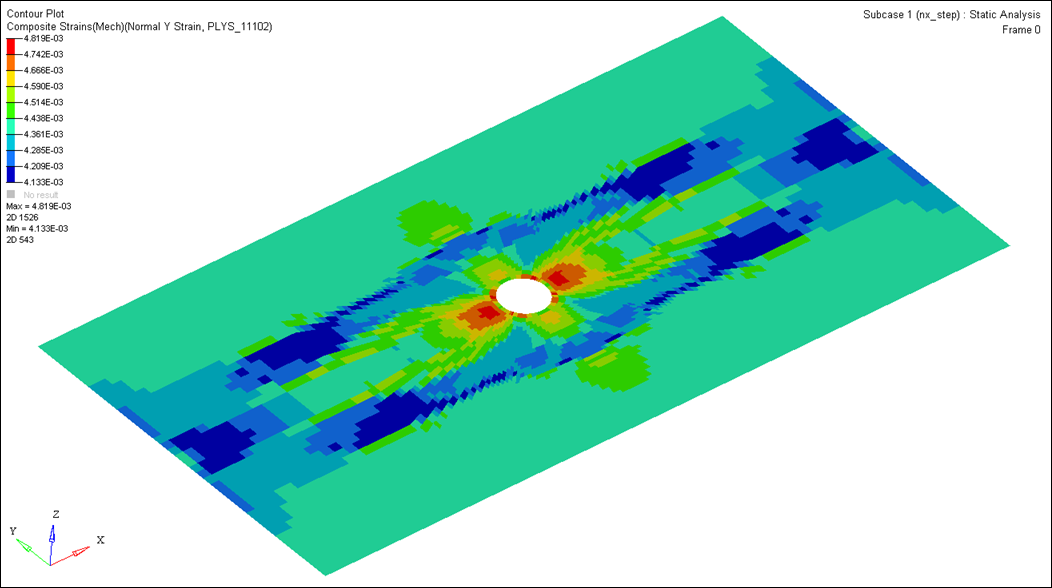
Set the Result type to Composites Strains(Mech) (s) and
the subtype to Normal Y Strain.
This corresponds to the matrix strain value.
To view the individual strain contributions from any one ply, select the
appropriate ply name in the Layers drop-down. Confirm that no ply exceeds 7000
microstrain (9e-3) for the matrix.
The final design weighs ~0.33 lbs.Figure 3. Maximum Normal Y Strain Across all Plies. No element exceed 0.007 me.

 .
A Select OptiStruct file browser opens.
.
A Select OptiStruct file browser opens.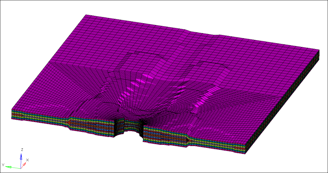

 to open the
Contour panel.
to open the
Contour panel.