
Model Setup and Baseline Analysis
The following set of steps completes the analysis setup of the initial model and provides a baseline analysis for comparison with the final optimized structure.
Launch HyperMesh and Set the OptiStruct User Profile
-
Launch HyperMesh.
The User Profile dialog opens.
-
Select OptiStruct and click
OK.
This loads the user profile. It includes the appropriate template, macro menu, and import reader, paring down the functionality of HyperMesh to what is relevant for generating models for OptiStruct.
Open the Model
- Click .
- Select the oht_analysis.hm file you saved to your working directory.
-
Click Open.
The oht_analysis.hm database is loaded into the current HyperMesh session, replacing any existing data.
Set Up the Model
Create Carbon Epoxy Material
-
In the Model Browser, right-click and select from the context menu.
A default material displays in the Entity Editor.
- For Name, enter carbonepxy.
- Set the Card Image to MAT8.
-
Enter the values shown in Figure 1.
Figure 1. 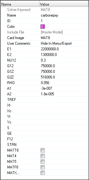
Create Element Set
-
In the Model Browser, right-click and select from the context menu.
A default set displays in the Entity Editor.
- For Name, enter ply_shape.
- Set the Card Image to SET_ELEM.
- For Entity IDs, click .
- Using the elems selector, select all of the elements in the model.
- Click proceed to continue.
Create Basic Plies
-
In the Model Browser, right-click and select from the context menu.
The Create Ply dialog opens.
-
Create a ply named ply1.
- For Name, enter ply1.
- Set the Material type to ORTHOTROPIC.
- Set Material to carbonepxy.
- For Thickness, enter 0.1.
- For Orientation, enter 0.0.
- Set the Shape selector to Set, then use the Sets selector to select the ply_shape set.
- Select Output results.
- Click Create.
Figure 2. 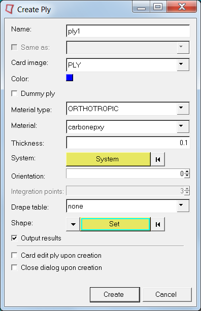
- Create a ply named ply2 with an orientation of 90.
- Create a ply named ply3 with an orientation of 45.
- Create a ply named ply4 with an orientation of -45.
- Click Close to exit the dialog.
Create Laminate
-
In the Model Browser, right-click and select from the context menu.
The Create Laminate dialog opens.
- For Name, enter laminate.
- Set Card image to STACK.
- Set Laminate option to Smear.
- In the Define laminate section, select ply1 for the first row, with each successive ply on a consecutive row. Leave all other parameters set as default.
- Click Create to create the laminate.
-
Click Close to exit
the dialog.
Figure 3. 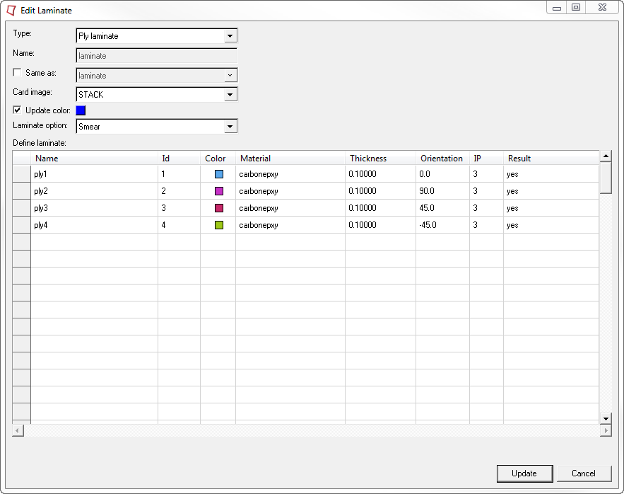
Create and Assign a Property
-
Create the property, laminate_property.
-
Assign elements to the property, laminate_property.
- In the Model Browser, Properties folder, right-click on laminate_property and select Assign from the context menu.
- In the panel area, use the elems selector to select all elements in the model.
- Click proceed.
Review the Model
-
On the Visualization toolbar, click
 to set the
element visualization mode to 2D Detailed Element
Representation.
This will thicken all shells in the model to their total thickness, displaying them as 3-dimensional representations of their thicknesses.
to set the
element visualization mode to 2D Detailed Element
Representation.
This will thicken all shells in the model to their total thickness, displaying them as 3-dimensional representations of their thicknesses. -
Click
 to set the
layers mode to Composite Layers.
This separates the view into individual plies.
to set the
layers mode to Composite Layers.
This separates the view into individual plies. -
Set the element color mode to By Prop.
This will assist you in determining which plies are which in the layup.Each of the plies in the model are color coded according to the color of its ply as shown in the Model Browser. If all of the plies in the model are the same color, change the ply colors in the Model Browser so that each is different to help differentiate the plies in the modeling window.
Figure 4. 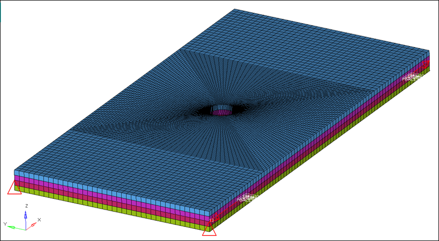
Create Output Requests
-
From the Analysis page, click the control cards
panel.
The Card Image dialog opens.
-
Edit the GLOBAL_OUTPUT_REQUEST card.
- Click GLOBAL_OUTPUT_REQUEST.
- Select CSTRAIN.
- Set EXTRA(1) to MECH.
- Set OPTION(1) to ALL.
- Select DISPLACEMENT.
- Set OPTION(1) to ALL.
- Select STRESS.
- Set OPTION(1) to NO.
- Click return.
This requests that NO homogeneous stress be output. This control card output must be explicitly added as a request since homogeneous stress is output by default. In turning it off, the values will not be calculated by the solver for output. -
Edit the OUTPUT card.
- Click return twice to return to the Analysis page.
Submit the Job
-
From the Analysis page, click the OptiStruct
panel.
Figure 5. Accessing the OptiStruct Panel 
- Click save as.
-
In the Save As dialog, specify location to write the
OptiStruct model file and enter
oht_analysis for filename.
For OptiStruct input decks, .fem is the recommended extension.
-
Click Save.
The input file field displays the filename and location specified in the Save As dialog.
- Set the export options toggle to all.
- Set the run options toggle to analysis.
- Set the memory options toggle to memory default.
- Click OptiStruct to launch the OptiStruct job.
View the Results
-
From the OptiStruct panel, click HyperView.
HyperView is launched and the results are loaded. A message window appears to inform of the successful model and result files loading into HyperView.
-
On the Results toolbar, click
 to open the
Contour panel.
to open the
Contour panel.
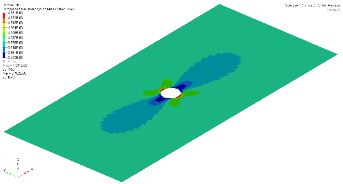
- Set the Result type to Composites Strains(Mech) (s).
- Set the subtype to Normal X Strain.
- To view the individual strain contributions from any one ply, select the appropriate ply name in the Layers drop-down.
- Click Apply.
Deactivate the Composite Visualization Enhancements
-
On the Page Controls toolbar, click
 to close the HyperView session and return to the
HyperMesh client.
to close the HyperView session and return to the
HyperMesh client.
-
On the Visualization toolbar, change the visualization settings.
- Set the element visualization mode to 2D Traditional Element Representation.
- Set the layers mode to Layers Off.
- Set the element color mode to By Comp.