OS-T: 3200 Design of a Composite Aircraft Underbelly Fairing
Composite materials have become popular in the application of aircraft structures. The need for innovative designs has posed a great challenge. In this tutorial you will perform an optimization-driven design approach of a composite aircraft underbelly fairing using OptiStruct.
- Phase 1: Reference Design Synthesis (Free-Size Optimization)
- Concept design synthesis Free-size optimization identifies the optimal ply shapes and locations of patches per ply orientation.
- Phase 2: Design Fine Tuning (Size Optimization)
- Design fine tuning Size optimization identifies the optimal thicknesses of each ply bundle.
- Phase 3: Ply Stacking Sequence Optimization
- Ply stacking sequence optimization Shuffling optimization obtains an optimal stacking sequence.
The process expands upon three important and advanced optimization techniques; free-size optimization, size optimization and ply stacking sequence optimization. By stringing these three techniques together, OptiStruct offers a unique and comprehensive process for the design and optimization of composite laminates. The process is automated and integrated in Altair HyperWorks by generating the input data for a subsequent phase automatically from the previous design phase.
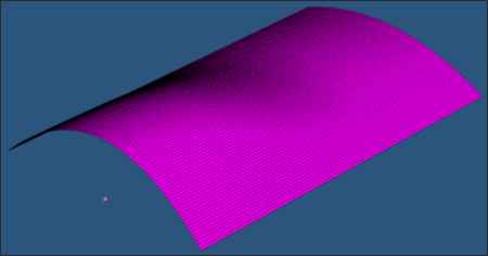
The finite element model of the underbelly fairing was generated in HyperMesh. Material properties for carbon-fiber were considered and represented using an orthotropic material (MAT8) for two dimensional elements. The fairing was modeled with four ply orientations (0°, 90°, 45° and -45°) of uniform thickness. The SMEAR option is applied in the PCOMP card to eliminate stack biasing.
