MV-1026: Model Curve-to-Curve (CVCV) Higher-Pair Constraint
In this tutorial, you will learn how to model a CVCV (curve-to-curve)
joint.
A CVCV (curve-to-curve) joint is a higher pair constraint. The
constraint consists of a planar curve on one body rolling and sliding on a planar curve
on a second body. The curves are required to be co-planar. This constraint can act as a
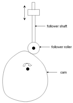
substitute to contact modeling in many cases where the contact occurs in a plane. One
such case is the cam-follower system, in which the follower is in the form of a roller.
Instead of modeling the contact between the cam and the follower, you can specify a CVCV
constraint between their profiles. Figure 1. In this tutorial, you will model a roller type cam-follower mechanism using a
CVCV constraint.
Create Points
In this step, you will create the points for the cam-follower model.
Before you begin, copy the files
CamProfile.h3d and CamProfile.csv, located
in the mbd_modeling\interactive folder, to your
<working directory>.
Start a new MotionView session.
Open the Add Point or PointPair dialog in one of the
following ways:
From the Project Browser right-click on
Model and select Add Reference Entity > Point.
On the Model-Reference toolbar, right-click the (Point) icon.
For Label, enter PivotPoint. Accept the default Variable
name.
Click OK.
Click the Properties tab and specify the X, Y, and Z
coordinates as 0.0.
Repeat steps 2
through 4 for the
points specified in Table 1.
Table 1.
Point
X
Y
Z
FollowerShaftCM
0.0
67.5
0.0
FollowerTransJoint
0.0
85.0
0.0
FollowerRevJoint
0.0
30.0
0.0
CamCM
0.0
-14.1604
0.0
Create Bodies
In this step you will create bodies for the cam-follower model.
You will use pre-specified inertia properties to define the bodies.
Open the Add Body or BodyPair dialog in one of the
following ways:
From the Project Browser right-click on
Model and select Add Reference Entity > Body.
On the Model-Reference toolbar, right-click on the (Body) icon.
In the dialog, add the Cam, FollowerShaft, and FollowerRoller bodies.
For the first Label, enter Cam. Click
Apply
For the second Label, enter FollowerShaft. Click
Apply.
For the third Label, enter FollowerRoller.
Click OK to close the
Add Body or BodyPair dialog.
The bodies you created will appear in the Model Tree under the Bodies folder.
In the Properties panel for each body:
Clear the Get Properties from associated
Graphic(s) check box.
Specify the CM Coordinate tab settings for the Cam body.
Check the Use center of mass coordinate system
box.
Double-click .
In the Select a Point dialog, choose
CamCM.
Click OK.
Accept the defaults for axes orientation properties.
Specify the CM Coordinate tab settings for the FollowerShaft body.
Check the Use CM Coordsys box.
Double-click .
In the Select a Point dialog, choose
FollowerShaftCM.
Click OK.
Accept the defaults for axes orientation properties.
Specify the CM Coordinate tab settings for the FollowerRoller body.
Check the Use CM Coordsys box.
Double-click .
In the Select a Point dialog, choose
FollowerRevJoint.
Click OK.
Accept the defaults for axes orientation properties.
Create Joints
In this step you will create joints for the cam-follower model.
You will define all joints except for the CVCV joint, which you will define
later.
Open the Add Joint or JointPair dialog in one of the
following ways:
From the Project Browser, right-click on
Model and select Add > Constraint > Joint.
On the Model-Constraints toolbar, click the (Joints) icon.
Create the CamPivot joint.
In the Add Joint or JointPair, for Label enter
CamPivot.
For Type, select Revolute Joint.
Click OK.
In the Connectivity tab, double click on and resolve it to
Cam.
Resolve to Ground Body and
click OK.
In the Connectivity tab, double click and resolve it to
PivotPoint.
Change the Alignment Axis to . Resolve Vector to Global
Z.
Create the FollowerTransJoint.
In the Add Joint or JointPair, for Label enter
FollowerTransJoint.
For Type, select Translational Joint.
Click OK.
In the Connectivity tab, double click on and resolve it to
FollowerShaft.
Resolve to Ground Body and
click OK.
In the Connectivity tab, double click and resolve it to
FollowerTransJoint.
Change the Alignment Axis to . Resolve Vector to Global
Y.
Create the FollowerRollerJoint.
In the Add Joint or JointPair, for Label enter
FollowerRollerJoint.
For Type, select Revolute Joint.
Click OK.
In the Connectivity tab, double click on and resolve it to
FollowerRoller.
Resolve to FollowerShaft and
click OK.
In the Connectivity tab, double click and resolve it to
FollowerRevJoint.
Change the Alignment Axis to . Resolve Vector to Global
Z.
Create Markers
In this step, you will create markers for the cam-follower model.
Open the Add Marker or MarkerPair dialog in one of the
following ways:
From the Project Browser, right-click on
Model and select Add > Reference Entity > Marker.
On the Model-Reference toolbar, click the (Marker) icon.
Create the CamMarker.
In the Add Marker or MarkerPair dialog, for Label
enter CamMarker.
Click OK.
In the Properties tab, double click on and resolve it to
Cam and click OK.
In the Properties tab, double-click and resolve it to
PivotPoint.
Click OK. Accept the
defaults for axes orientation.
Create the FollowerMarker.
In the Add Marker or MarkerPair dialog, for Label
enter FollowerMarker.
Click OK.
In the Properties tab, double click on and resolve it to
FollowerRoller and click OK.
In the Properties tab, double-click and resolve it to
FollowerRevJoint.
Click OK. Accept the
defaults for axes orientation.
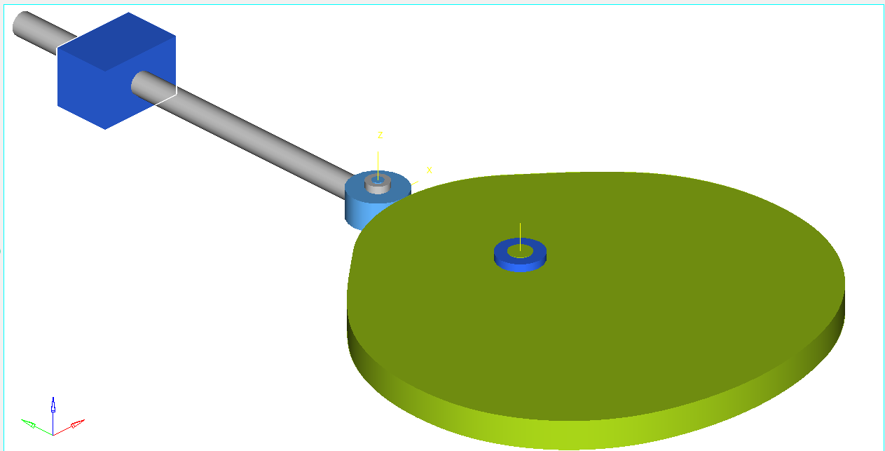
Create Graphics
In this step you will create graphics for the bodies and joints in the cam-follower
model.
Use the provided h3d file for the cam graphics. The follower shaft and roller can
be represented with primitive graphics.
Open the Add Graphics or GraphicPair dialog in one of the
following ways:
From the Project Browser, right-click on
Model and select Add > Reference Entity > Graphics.
On the Model-Reference toolbar, click the (Graphics) icon.
From the dialog, for Label, enter Cam.
From the drop-down menu, click File.
Figure 2.
Click the (File Browser) icon and open the
CamProfile.h3d from the model folder.
Click OK.
In the Connectivity tab, double-click on and
resolve the graphic to the Cam body.
Repeat step 1 to
create another graphic. For Label, enter
FollowerShaft.
From the drop-down menu, select Cylinder and then click
OK.
In the Connectivity tab, double-click on and
resolve the graphic to the FollowerShaft body.
Double-click on and choose FollowerShaftCM.
Then click OK.
Change the Alignment Axis to .
Resolve Vector to Global Y.
In the Properties tab, specify the values in Table 3.
Table 3.
Property
Value
Length
75
Offset
-37.5
Radius 1
2.000
Radius 2
2.000
For Cap Properties, choose Cap Both Ends.
Repeat step 1 to
create another graphic. Use the specifications given in Table 4 and Table 5.
Table 4.
Name
Type
Direction ()
FollowerRoller
Cylinder
FollowerRoller
FollowerRevJoint
Global Z
Table 5.
Property
Value
Length
5.0
Offset
-2.5
Radius 1
5.000
Radius 2
5.000
For Cap Properties, choose Cap Both Ends.
Create CamPivotGraphicOne and
CamPivotGraphicTwo using the specifications in Table 6 and Table 7.
Table 6.
Name
Type
Direction ()
CamPivotGraphicOne
Cylinder
Ground Body
PivotPoint
Global Z
CamPivotGraphicTwo
Cylinder
Cam
PivotPoint
Global Z
Table 7.
Name
Property
Value
CamPivotGraphicOne
Length
7.5
Offset
-3.75
Radius 1
4.000
Radius 2
4.000
CamPivotGraphicTwo
Length
7.6
Offset
-3.8
Radius 1
2.000
Radius 2
2.000
Create RollerPivotGraphicOne and
RollerPivotGraphicTwo.
Put RollerPivotGraphicOne on the FollowShaft. In
Properties, specify a length of 7.5 and a radius
of 2.
Put RollerPivotGraphicTwo on the FollowerRoller.
In Properties, specify a length of 7.6 and a
radius of 1.
Create the FollowerTransJointGraphic.
In the Add Graphics or GraphicPair dialog, select
Box.
In the Connectivity tab, double-click on and resolve the graphic to the
Ground Body.
From the Type drop-down menu, click
Center.
Double-click on and choose
FollowerTransJoint. Then click
OK.
Under axis orientation, for the Z-axis choose the vector
Global Z and for the ZX plane choose the
vector Global X.
From the Properties tab, specify the values in Table 8.
Table 8.
Property
Value
Length X
15
Length Y
10
Length Z
10
You model should look like the example in Figure 3.Figure 3.
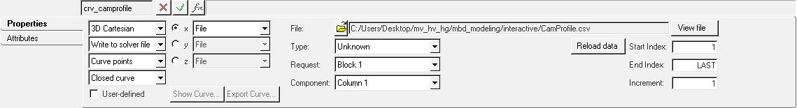
Create Curves
In this step you will create the curves that define the cam and the
roller.
You have been provided with data for the cam profile curve in
.csv format. The roller profile is circular, so you can define
it with a mathematical expression.
Open the Add Curve dialog by doing one of the
following:
From the Project Browser, right-click on
Model and select Add > Reference Entity > Curve.
On the Model-Reference toolbar, click the (Curves) icon.
For Label, enter CamProfile and click
OK.
In the Properties tab, click the first drop-down menu and change the curve from
2D Cartesian to 3D Cartesian.
Click the fourth drop-down menu and set the curve type to Closed
curve.
Click the x radio button.
Click and open CamProfile.csv.
Choose the properties of the curve given in Figure 4.
Figure 4.
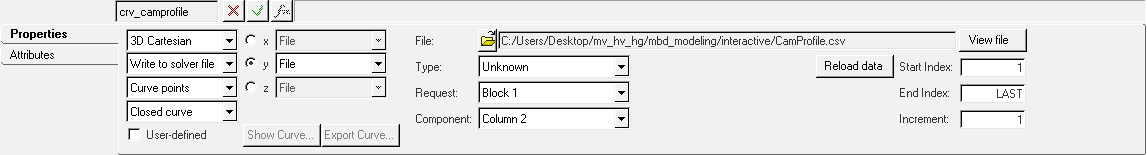
Click the y radio button. Change the Component to
Column 2.
Figure 5.
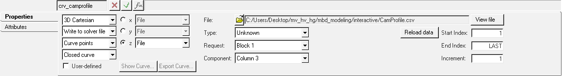
Click the z radio button. Change the Component to
Column 3.
Figure 6.
Repeat step 1. In
the dialog, for Label enter FollowerRollerProfile.
Click OK.
In the Properties tab, click the first drop-down menu and change the curve from
2D Cartesian to 3D Cartesian.
Click the fourth drop-down menu and set the curve type to Closed
curve.
Click the x radio button. In the drop-down menu, click
Math.
In the Expression Builder, enter
5*sin(2*PI*(0:1:0.01)).
Click the y radio button and choose
Math in the drop-down menu.
In the Expression Builder, enter
5*cos(2*PI*(0:1:0.01)).
Click the z radio button and choose
Math from the drop-down menu.
In the Expression Builder, enter 0.0*(0:1:0.01).
Create the CVCV Joint
In this step you will create the CVCV (curve-to-curve) joint.
Open the Add AdvJoint dialog by doing one of the
following:
From the Project Browser, right-click on
Model and select Add > Constraint > Advanced Joint.
On the Model-Reference toolbar, click the (Advanced Joint)
icon.
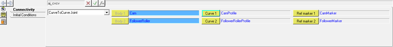
In the dialog, for Label enter CVCV.
Choose CurveToCurveJoint in the drop-down menu and click
OK.
In the Connectivity tab, double-click each collector (, , ,
) and specify the connections shown in Figure 7.
Figure 7.
Specify the Cam Motion
In this step, you will specify a motion for the cam using an expression.
Open the Add Motion or MotionPair dialog by doing one of
the following:
From the Project Browser, right-click on
Model and select Add > Constraint > Motion.
On the Model-Reference toolbar, click the (Motion) icon.
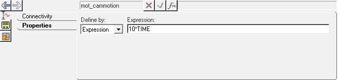
In the dialog, enter the Label CamMotion and click
OK.
In the Connectivity tab, double-click . Choose CamPivot and click OK.
in the Properties tab, in the drop-down menu define the motion by
Expression.
Enter `10*TIME` in the Expression field.
Figure 8.
Specify Gravity
In this step you will specify gravity for the model in the negative Y
direction.
In the Project Browser, click to expand Misc. > Forms.
In the Forms folder, click Gravity. In the panel,
specify the following values:
X Component = 0
Y Component = -9810
Z Component = 0
Specify Output Requests
In this step, you will specify output requests.
Open the Add Output dialog by doing one of the
following:
From the Project Browser, right-click on
Model and select Add > General MDL Entity > Output.
On the General toolbar, click the (Outputs) icon.
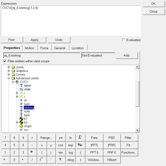
In the dialog, for Label enter CVCV Reaction and click
OK.
In the Properties tab, from the drop-down menu define the output by
Expression.
Click in the F2 field to activate the button.
Click the button.
In the Expression Builder, populate the expression as
'CVCV({aj_0.idstring},1,2,0)'.
Figure 9.
Click OK.
Repeat steps 4
through 6 for F3,
F4, F6, F7, and F8 by changing the third parameter in the expression to
3, 4,
6, 7, and 8
accordingly.
The CVCV (id, jflag,
ref_marker) function returns the reaction on the CVCV
joint:
id ID of the CVCV joint
jflag 0 gives reaction on the I-marker and 1 on
J-marker
comp component of the reaction
ref_marker reference marker (0 implies Global
Frame)
Run the Model
In this step you will run the cam-follower model.
On the toolbar, click (Run).
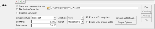
In the Run panel, specify the values shown in Figure 10.
Figure 10.
Click the Save and run current model radio button.
Click the (browser icon) and specify a name for the solver
file.
Click Save.
Click the (Check Model) button to check the model for
errors.
To invoke the solver, click the Run button.
Once the solver has finished, click the (Start/Pause Animation) button to view the
animation.
View the Results
In this step you will learn how to view the animation and plot the Y displacement of
the follower.
Once the solver has finished, the Animate button will be active. Click on
Animate.
Click the (Start/Pause Animation) button
to view the animation.
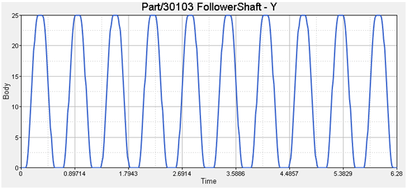
One would also like to inspect the displacement profile
of the follower in this mechanism. For this, you will plot the Y position of
the center of mass of the follower.
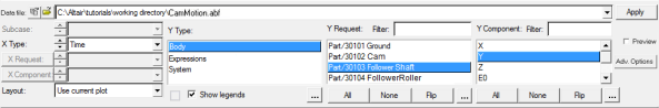
From the Page Controls toolbar, click > . Click in the window on the lower right to make it the active
window.
In the Select application drop-down menu, change the client from MotionView to HyperGraph 2D.
On the Curves toolbar, click
(Build Plots).
Click the (file browser) and open the
results.abf file.
Click Apply. This will plot
the Y profile of the center of mass of the follower.
The profile for the Y displacement of the follower should look like the
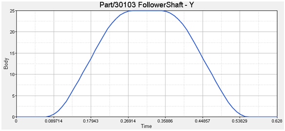
example in Figure 12. Figure 12. Set the X-axis properties to zoom in on one cyle and the profile will look
like the example in Figure 13.
Figure 13.
Check the Model for Potential Lift-Off
In this step, you will check the cam-follower mechanism for potential lift-off by
plotting the Y profile of the CVCV reaction on the follower roller.
In some cases, the dynamics of the system may cause the follower to lose contact
with the cam. This is called ‘lift-off’. In such cases, modeling the system with a CVCV
will give you incorrect results because the joint constrains the follower point to
always be on the curve (and hence cannot model lift-offs). For such cases, you must use
contact modeling (refer to MV-1010: 3D Mesh to Mesh Contact Simulation). However, you will want to
start with a CVCV model since it is a lot easier than modeling contact. Given this
scenario, model the system using a CVCV joint and monitor the CVCV joint reaction. If
the reaction on the follower is a ‘pulling’ reaction, this indicates lift-off would have
occurred and you must switch to a contact model. Otherwise, the contact model is
unnecessary. Now, you will check the model you used in the tutorial. The follower is
moving along the Y-axis, so any negative reation along the Y-axis is a 'pulling'
reaction.
Click (Add Page) to add a new page to the session.
Switch the client to HyperGraph 2D.
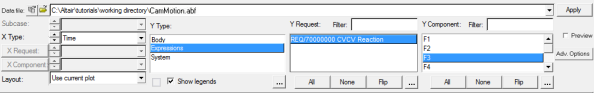
Click on (Build Plots).
Click on (browser icon) and load the
results.abf file.
Click OK to plot the Y
profile of the CVCV reaction on the follower roller.
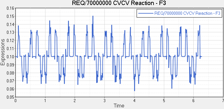
Figure 15.
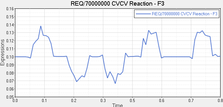
Scale the x-axis to view one cycle on the profile.
Figure 16. As shown in Figure 16, the Y component of the CVCV reaction on the follower is always positive.
There is no pulling reaction, so the CVCV model is acceptable for this
mechanism.

 (Point) icon.
 (Body) icon.
 .
.
 (Joints) icon.
  and resolve it to
Cam.
and resolve it to
Cam.
 to Ground Body and
click OK.
to Ground Body and
click OK.
 . Resolve Vector to Global
Z.
. Resolve Vector to Global
Z.
 (Marker) icon.
 and resolve it to
Cam and click OK.
and resolve it to
Cam and click OK.
 (Graphics) icon.
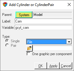
 (File Browser) icon and open the
CamProfile.h3d from the model folder.
(File Browser) icon and open the
CamProfile.h3d from the model folder.
 (Curves) icon.
 and open CamProfile.csv.
 (Advanced Joint)
icon.
(Advanced Joint)
icon. ,
,  ,
,  ,
,
 ) and specify the connections shown in Figure 7.
 (Motion) icon.
 . Choose CamPivot and click OK.
 (Outputs) icon.
 button.
 (Run).
 (Check Model) button to check the model for
errors.
(Check Model) button to check the model for
errors.
 (Start/Pause Animation) button to view the
animation.
(Start/Pause Animation) button to view the
animation.
 >
>  . Click in the window on the lower right to make it the active
window.
. Click in the window on the lower right to make it the active
window.
 to HyperGraph 2D
 .
.
 (Build Plots).
 (Add Page) to add a new page to the session.