
MV-5000: Rigid Body Animation (Basic)
Tutorial Level: Beginner Learn how to use some features available for post-processing animation results in HyperView, and how to control the display of the simulation results using Entity Attributes.
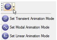
| Transient | Transient animation displays the model in its time step positions as calculated by the analysis code. Transient animation is used to animate the transient response of a structure or multibody system | |
| Linear | Linear animation creates and displays an animation sequence that starts with the original position of the model and ends with the fully deformed position of the structure or multibody system. An appropriate number of frames are linearly interpolated between the first and last positions. Linear animation is usually selected when results are from a static analysis. | |
| Modal | Modal animation creates and displays an animation sequence that starts and ends with the original position of the structure or multibody system. The deforming frames are calculated based on a sinusoidal function. Modal animation is most useful for displaying mode shapes. |
The tables below show the animation analysis types, mode settings, and the
model and results file types required to animate MotionSolve and ADAMS
results.
| Multibody Analysis Type | Animation Mode Setting | Parts in Model | Model File | Results File |
|---|---|---|---|---|
| Transient/Static/Quasi-Static | Rigid or Flexible Bodies | H3D | H3D | |
| Linear | Rigid or Flexible Bodies | H3D | H3D |
| Multibody Analysis Type | Animation Mode Setting | Parts in Model | Model File | Results File |
|---|---|---|---|---|
| Transient/Static/Quasi-Static | Purely rigid | GRA | GRA | |
| Transient/Static/Quasi-Static | One or more flexible bodies | FLX | FLX | |
| Linear | Purely rigid | GRA | RES | |
| Linear | One or more flexible bodies | FLX | FLX |
View and Control Animation Files
View and control the pendulum animation based on the files output by MotionSolve.
-
From the menu bar, click .
Note: If a warning message is displayed, asking if you want to discard the current data, click Yes to continue.
-
Click the Select Application drop-down menu and choose
 (HyperView).
-
On the Standard toolbar, click the
 (Load Results) icon.
Figure 2. Load model and results panel 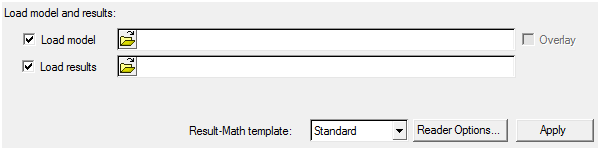
-
In the panel that appears, click the Load model file
browser
 and select the file
single_pendulum.h3d from your <working
directory>.
The Load results field will be automatically populated with the same path and name.
and select the file
single_pendulum.h3d from your <working
directory>.
The Load results field will be automatically populated with the same path and name. -
Click Apply.
HyperView loads the animation file.
-
On the Standard Views toolbar, click the
 (XZ Left Plane View) to change
to the left view of the model.
(XZ Left Plane View) to change
to the left view of the model.
-
Click the
 (Start/Pause Animation) button
on the Animation toolbar to start the animation.
(Start/Pause Animation) button
on the Animation toolbar to start the animation.
-
Right-click
 (Fit Model/Fit All Frames) on
the Standard Views toolbar to fit the entire animation in the window.
(Fit Model/Fit All Frames) on
the Standard Views toolbar to fit the entire animation in the window.
-
On the Animation toolbar, click
 (Animation Controls).
In the panel that appears, you can control parameters like speed, start time, and end time of the animation.
(Animation Controls).
In the panel that appears, you can control parameters like speed, start time, and end time of the animation.Figure 3. Animation Controls panel 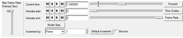
- Drag the vertical slider bar on the left to change the animation speed from fast to slow.
- Current time: show all the time steps.
- The Animate start and Animate end sliders can be set to restrict the animation to a certain window in time. For example, moving the start slider to 0 and end slider to 3.5 to restrict the animation to these time limits and covers only a partial cycle of motion.
-
Click the
 (Start/Pause Animation) button
on the Animation toolbar to stop the animation.
(Start/Pause Animation) button
on the Animation toolbar to stop the animation.
Trace Entities
Trace the path of a moving part while Animating using HyperView.
- Retain the animation file single_pendulum.h3d that was loaded in the step View and Control Animation Files.
-
To trace the pendulum motion, click the
 (Tracing) button.
Figure 4. Tracing panel 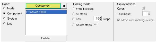
- Under Trace select the Component radio button.
- Pick the entity/component that needs to be traced by clicking on it from the modeling window.
-
Change the view to the
 (Iso) view.
- Under Tracing mode select Last and specify 10 as the steps.
-
Animate the model.
This displays the last 10 steps in the animation.
- To turn the tracing off, click the Delete button to remove the selected components from the tracing list.
- Try the From First Step and All Steps options.
- Use the Display Options to change the line color and thickness.
Track Entities
Track one part of the animation.
-
On the Page Controls toolbar, click the
 (Add Pages) icon to add a page to your session.
- Load the animation file front_ride.h3d from your <working directory>.
-
On the Results toolbar, click the
 (Tracking) button.
Figure 5. Tracking panel 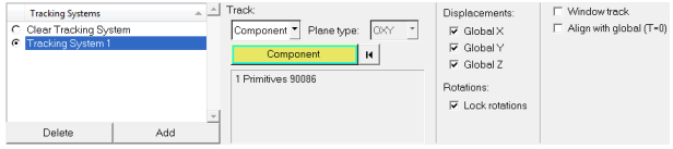
The Tracking panel allows you to track or fix any part of your model in the center of the animation window and to see all the other parts moving with respect to the fixed part.
- Under Tracking Systems, click the Add button to add a tracking system to the animation.
- In the Track pull-down menu, select Component. Then click on any part of the model currently loaded.
- Select the Displacements and/or Rotations to track the selected part.
-
Click the (Start/Pause Animation) button
on the Animation toolbar to start the animation. Click the button again to stop/pause the animation.
Edit Entity Attributes
Edit the graphic entity attributes.
- Retain the model front_ride.h3d loaded in the step Track Entities.
-
On the Visualization toolbar, click the
 (Entity Attributes) panel button.
Figure 6. Entity Attributes panel 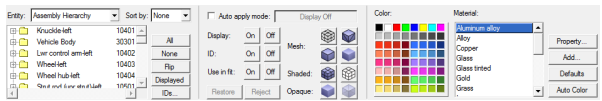
-
In the panel, click the arrow to the right of the Entity
option menu to expand it.
The list contains the following entity types: Components, Systems, Assembly Hierarchy, and Sets.
- Select Assembly Hierarchy from this list to show all the parts of the model in the entity list tree below.
-
Change the color of the model.
- From the Entity option menu, select Assembly Hierarchy.
- Next to the entity list tree, select the All button.
- Under Color, select a color from the palette.
-
Change the model to wire frame.
- Next to the entity list tree, select theAll button.
-
Click the
 (Wire Frame) icon.
-
Make the model transparent and shaded.
- Next to the entity list tree, select theAll button.
-
Click the
 (Shaded) icon.
-
Click the
 (Transparent)
icon.
(Transparent)
icon.
- Use the On/Off buttons to turn the entities on or off.
- Use the On/Off buttons next to ID: to display and hide the entity IDs.