This technique is used primarily with kinematic mechanism models, such as systems
with zero degrees of freedom. Typically, one of the inputs links is provided an
input motion. The task at hand is to compute the link lengths so that an output
point on one of the other links follows a prescribed path.
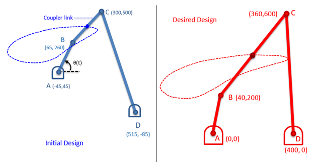
Consider the 4-bar mechanism shown on the left below. An input θ(t) is provided to
link AB. As link AB rotates about its pivot, the midpoint of the coupler link
traverses a path shown as a dashed blue line.Figure 1.
Design Objective
Determine the link lengths of the 4-bar mechanism so that the midpoint
of the coupler link traverses the path shown in the image on the right,
in red.
Design Variables
The locations of points A, B, C and D that determine the link
lengths.