Altair HyperMesh 2023 Release Notes
Aeroelasticity
New Features
Supported CAERO2 and PAERO2 cards for OptiStruct support that includes I/O, context GUI and browser listing and manipulation.
Enhancements
Supported duplicate ID for elements across structure and Aeroelasticity module. Aero components and elements created during meshing are always appended to the database. No gap ID filling is available.
Resolved Issues
- Failure in aeroelasticity meshing while geometric dimensions are numerically very small is resolved.
- Failure to import aeroelastic data with include files is resolved.
API
- Automation Release Highlights
- Watch this video to learn more about Automation features in 2023.
- HyperMesh Panel APIs
- The HyperMesh panels have been completely removed together with all the related API commands and command options. All the details are included in the API Programmer's Guide section of the HyperMesh Reference Guide.
- Changes to hm_framework command
- When using hm_framework command options addpanel and
drawpanel, the Tk frame supplied to the command
must be empty and populated afterwards.
For more details and the full list of changes, new features and enhancements, see the 2023 API Programmer’s Guide section of the HyperMesh Reference Guide.
Browsers
New Features
- Card Editor
- A new Entity Editor-style Card Editor includes enhanced functionality for editing solver entities in the solver deck format.
-

Figure 1. - Export to CSV/HTML from Hierarchy Browsers
- The capability to export browser data as reports in CSV or HTML format is now supported across all hierarchy browsers, which allows you to extract and save the data from various browser views in a convenient and shareable format.
-

Figure 2.
Enhancements
- Browser/Idle Selector Sync
- This two-way sync between the Browser and Idle Selector ensures that they are always in sync.
- Card Image/Config Column
- Card Image or Config (depending on the specific entity type) is added as a default column in the respective entity browsers and advanced selection dialogs to review or select entities based on the Card Image or Config.
Known Issues
- The Entity Editor is not cleared when the entity is removed from the filtered browser list.
- The keyword list for the Create menu is removed from entity views upon loading a model.
Resolved Issues
- Performance issue with opening the Equations Browser.
- Performance issue with invoking context menu on the Loads folder.
- Hiding Load Step does not hide the referenced Loads/Load Collectors.
- Card Image column was missing in the Advanced Selection dialog.
- Incomplete data export (*.csv) from the Mass Summary tool.
- Elements were put in low light upon invoking the References Browser.
- Rename By ID considers the ID even when it's not input.
Certification
Resolved Issues
- A critical bug with unordered points in the JointLoad method has been resolved.
- Wrong results were given in the event of designpointsets populated with designpoint IDs (fasteners) in non-increasing order.
- Issues in the Method Contouring tool have been resolved.
- The Method Contouring tool allows contouring “Critical ply id” and “Critical material id” (was broken in 2022.3).
- The layer list filter in the Method Contouring tool is again populated for all use cases (broken in 2022.3).
Composites
New Features
- Composite Stress Toolbox
- With the Composite stress toolbox, you can do model post-processing with contour plots.
- Elements can be selected from the contour plot for detailed
post-processing with full tabular results and through-thickness
plots.

Figure 3.
Enhancements
- Composite Stress Toolbox
- Engineering constants include out-of-plane shear properties.

Figure 4. - Injection Mold Mapping
- Shell element mapping support added in the OptiStruct profile.
Known Issues
- Composite Stress Toolbox
- Derived load cases not yet supported.
Resolved Issues
- Composite Stress Toolbox
- All analyses utilize the full DRAPE table information (n slices) as opposed to single DRAPE entry.
- Certification - Model Contouring Tool
- The Method Contouring Tool allows contouring “Critical ply id” and “Critical material id” again (broken in previous minor release).
Connectors
New Features
- Added apply mass controller to replace the apply mass panel.

Enhancements
- Metal Clip Enhancements
-
- Added an option for determining the hole nodes.
- Added an option to offset the cylindrical selection horizontally.
- Stitch HL Enhancements
-
- Stitch HL can now have more than two links.
- Node selection is available during absorption for Stitch HL.
- HAZ size is now dependent on the plate thickness.
- Stitch HL can now be split.
- Other Enhancements
-
- Miscellaneous enhancements to CWELD and CFAST realizations.
- Absorb now supports elements and nodes as link types.
- Absorb correctly assigns element type for core configs that support changing the element type.
- RBE3 Connect tool retains the selection.
- Rebuild option is now set as default in various configs for the "After Imprint" and "Unrealize Remesh or Rebuild" attributes.
- xMCF now supports Weld Database file support
- Connector control file auto-loaded from the Absorb GUIs as well
- MAT8 and PSHELL for Huth/Rutman Formulation is now calculated as a Composite.
- CFAST Element System is now available for Huth realization.
Resolved Issues
- Fixed an issue where some blind drill holes were not recognized.
- Fixed issues regarding crashes when realizing or absorbing connectors.
- Resolved issue with PSOLID as the first link on a connector.
Design Explorer
New Features
- Design Explorer Release Highlights
- Watch this video to learn more about Design Explorer features in 2023.
- Response Creation from HW Session File
- This feature builds upon the generic response creation added in the HyperWorks 2022.3 release. With this enhancement, you can define responses and goals within a HyperWorks session, and then add and use them in their explorations in Design Explorer. Define and use any response that can be evaluated within the TableView client of the HyperWorks session based on plots, animations, and any corresponding calculations.
- Automatic Design Variable Link Creation
- Using shape matching AI, you can automatically link symmetric matching parts from their exploration design variables, saving the time and effort spent previously, and eliminating potential human error. A preview feature allows for a visual preview of matching parts before links are created.
- Curve Prediction
- Viewing real time predictions of response curves is now available.
Moving the design variable value sliders will update the predicted curve
according to the current slider values. With the new curve predictions
being added alongside existing scalar and field predictions already
available, Design Explorer now supports a complete set of predictive
tools.

Figure 5. - ExpertAI
- ExpertAI uses the clustering tools added to the Design Explorer in HyperWorks 2022.3 and allows leveraging clusters as a constraint in an optimization. The ExpertAI workflow provides the opportunity to ensure that their designs are not only optimal but that they also conform to desired criteria such as a particular deformation mode which could not otherwise be guaranteed through optimization alone.
Extensions
Highlights
- Extensions Release Highlights
- Watch this video to learn more about Extension features in 2023.
- Autoloading of extensions of newly added Extensions
Enhancements
- Autoload Extensions
- Extensions can be autoloaded using the “extends” entry when the
application starts or is loaded with the environment variable
HWX_PLUGINS. - To load all referenced profiles/sub-profiles, the value
“HyperWorksDesktop” should be used, the extension can not be unloaded if
loaded via the “extends” entry.

Figure 6.
Known Issues
- To show the Extension loaded in different profiles even when no GUI access
points like ribbons, toolbars or menus are available requires that each
profile is loaded with at least one entry. The example below shows the empty HyperMesh and HyperView profiles with the (dummy) entry resources. This entry will not be required in future versions to show the extension loaded in these profiles.

Figure 7.
Resolved Issues
- The “displayName” is no longer the same as the “name”
Fields
Enhancements
- Updated Convection Mapping
- Convection mapping now leverages the new OptiStruct CONVG load entity, which also results in much faster realizations for large models.
- Faster Force Mapping
- Improved force balance method for better reliability and faster realization times with large models.
Resolved Issues
- Corrected bug that was causing scale factors to be applied twice with repeated realizations.
- Corrected issue with tolerance not updating.
- Corrected application error when clicking on some parts of the realization dialog.
General
New Features
- HyperMesh Release Highlights
- Watch these videos to learn more about new HyperMesh features in 2023.
- Keyboard Shortcuts Editor
- HyperMesh shortcuts are now configurable using the new
Keyboard Shortcuts Editor. Access it from the
View menu to review and edit existing shortcuts, or create new ones.
Shortcuts can be assigned to a list of registered application tools and
functions, as well as custom Python or Tcl scripts.

Figure 8. - Position Tool
- A new Position mode is added to the Move tool. In this mode, you can
position the selected entities by picking one, two, or three source and
target location pairs. The source locations represent starting reference
points, which are matched with their corresponding targets to produce a
transformation.

Figure 9. - Calculate Workflow
- New COG and MOI calculation options have been added to:
- Calculate values in a local coordinate system.
- Calculate MOI around coordinate system center or COG.
- Consider lumped mass in COG and MOI calculations (valid for Radioss and LS-DYNA profiles only).

Figure 10.
Figure 11. - Quick Advanced Selection Menu (Alt+Select)
- It is now possible to switch the active Quick Advanced Selection method
(Alt+Select) for any current selection via this new quick menu,
accessible via the comma ( , ) key. The shortcut for this function is
also configurable in the new Keyboard Shortcut
Editor.

Figure 12. - Ribbon Hints
- Ribbon hints have been added to help identify tools that have multiple
pick targets or open a secondary ribbon. They are small indicators that
appear in the ribbon between a tool’s icon and label. The number of dots
represents the number of pick targets in a tool, including some that are
hidden until hovering over the tool.

Figure 13.
Enhancements
- Improvements to invoke speed.
- General performance improvements in user interaction with graphics/GUI (menus, guide bars, dialogs, model manipulation, and so on).
- Default shortcuts for the following selection actions have been reassigned:
- Advanced Selection (configurable): period ( . )
- Quick Advanced Selection menu (configurable): comma ( , )
- Selection Search (Entity Editor only, not configurable): forward slash ( / )
- Selection is now restored on undo for ordered and topology-based selectors.
- Hovering over curved lines shows the line length along with the radius.
- New shortcuts added for the Save selection and Retrieve selection actions: Ctrl+W and Ctrl+Shift+W.
- Drag and drop action is now supported for session files & Python scripts. Auto color now uses a random color palette that makes use of our expanded RGB colors.
- Newly created collectors or imported files with no color data are assigned colors from our accessibility color palette that are more visible in light/dark theme and by individuals with some types of color blindness.
- The context menu is now accessible in more selectors, regardless of their UI modality state.
- Current Collector selectors in the status bar area have new options to toggle entity icons, color, and show/hide IDs; they also make better use of available space for names and IDs. The new options are available in .
Known Issues
- File Open/File Save Dialogs and
Message Boxes:
- There are inconsistencies seen in the appearance of the following
types of dialogs:
- File Open
- File Save
- Message Boxes
- Based on the available file extension filters in File Open and File Save dialogs, and how those dialogs or a message box are brought up, the appearance/style of the dialog can differ from other instances of those dialogs.
- Some of these dialogs can go behind the main application when clicking elsewhere in the application, requiring you to bring them back to the foreground or reposition the application.
- Example showing the different versions of the File
Open dialog:

Figure 14.
Figure 15.
- There are inconsistencies seen in the appearance of the following
types of dialogs:
- When running in a NICE/DCV environment, there are drawing issues with the HyperWorks Toolbelt and Advanced Capture.
- Any legacy or custom Tk dialogs which may have been coded to operate using hard-coded keyboard shortcuts continue to expect the originally designated shortcut key, even if an equivalent HyperMesh shortcut has been edited using the Keyboard Shortcut Editor.
- HyperWorks may hang on re-launch if the license is close to expiring and the
license expiration warning dialog appears after a non-default browser was
active on previous shutdown.
- To avoid this, one of the following environment variables can be
used:
- ALM_NO_EXPIRE_WARNING: Disables the expiration warning.
- ALM_EXPIRE_DAY_WARNING: Specifies the number of days before license expiration warning message is given (default is 30).
- If one of the environment variables listed above is not used to avoid the issue, and the issue is seen, deleting the settings files resolves the issue.
- To avoid this, one of the following environment variables can be
used:
- For Windows 11: On a multi-window page with two or more HyperMesh windows
and at least one HyperView window, sometimes loading a model via the
File Open dialog launched from HyperView's Load
Model panel does not properly update the panel with the file name. This
prevents you from loading the file.
- If this issue is seen, you can load the file by copying and pasting, or directly typing the file path/name into the Open Model panel and clicking Apply.
- The HyperMesh session can freeze if you open the File menu while the Import Options dialog is launching (but before it is displayed). If this happens, switch to another application and then return to HyperMesh to resolve the issue.
- Launch times for HyperMesh have improved compared to those seen in 2022.3 for the new interface. However, there is still ongoing activity to further improve, particularly on first invoke, for certain network configurations.
- In multi-window layouts, longer guide bars may be truncated. To resolve the issue, resize the modeling window to be wider or expand the window so the guide bar is able to expand completely.
- Launch times for HyperMesh have improved over those seen in 2022.3 for the New HyperMesh. However, there is still ongoing activity to make additional improvements, particularly on first invoke, for certain network configurations.
- In multi-window layouts, longer guide bars may be truncated. To resolve this issue, resize the graphics area to be wider, or expand the window so that the guide bar is able to draw completely when it's accessed.
- If the advanced color selector is opened from the modeling window context menu, typing in the edit fields (red, green, blue, hex) is not possible; the arrow buttons can still be used to increment/decrement the red/green/blue values. To avoid this issue, open the color selector by clicking on the color in the browser or Entity Editor instead of from the modeling window context menu.
- In certain use cases, the outputs pushed to the Tcl Command Window during script execution are delayed until the script has finished. As a temporary solution, replace the stdout channel with a user-defined opened channel, then push the information to a text file.
- In certain cases, when launching directly into a post client (HyperView, HyperGraph, and so on) using the -clientconfig command line option, the client-specific browser cannot be opened. To avoid this, use the provided client-specific launch scripts (hv, hg, and so on) instead of the -clientconfig command line option.
- The LMB+RMB mouse customization does not work and will be disabled this release.
- After switching from HyperMesh to one of the post clients (HyperView, HyperGraph, and so on), certain function keys not used as shortcuts in the clients can open the HyperMesh secondary ribbon with blank icons or exit the idle context. To resolve this issue, switch to a context available within the client and then exit the context.
- On Windows, a segmentation error on shutdown can occur if HyperGraph, HyperView, or MotionView is opened from the Start menu, MediaView is opened from the Startup dialog, and the client is changed to HyperMesh before shutting down. To avoid this error, select HyperMesh from the Start menu instead of HyperGraph, HyperView, or MotionView, and open MediaView from the Startup dialog.
- After exiting HyperMesh on Linux, error messages can be seen in the terminal window if the session has been left idle for some time.
Resolved Issues
- Batch mode (-b) is now working for the new interface.
- Capturing images in dark theme when publishing now maintains the dark background instead of switching to a white background.
- Drag-and-drop of .hm and .mvw files into the modeling window on Linux is now working.
- There is no longer an error when importing/opening files from a directory with non-ASCII characters in the path on Linux.
- Many cases of dialogs/context menus coming up on the incorrect monitor in a multi-monitor setup have been resolved.
- When entering the Show/Hide tool, previous selections are not automatically carried into the tool anymore (this was causing them to be hidden immediately after entering the tool).
- Fixed an issue with some Rigid Body entities not being available for selection in the modeling window when outside of a tool.
- Fixed some inconsistent entity names between browser and modeling windows.
- Performance issue while populating Organize Reference dialog when moving components between includes.
- Tag color changes when you move the associated node.
- ModelChecker is adding messages on the status bar when selecting elements.
- HyperMesh model read performance is improved.
Geometry
New Features
- Geometry Release Highlights
- Watch this video to learn more about Geometry features in 2023.
- Sketching in one modeling window within HyperMesh shows existing geometry in the background.
- Extract Lines at intersection of two planes, planes/surfaces, planes/elements, and surface/surface.
- Extract Nodes/Points at intersection of two planes or planes with lines, surfaces, or solids.
- Faces, edges, and equivalence have new context menus available to check and fix mesh connectivity issues.
- The Detach elements workflow is migrated under the Topology Detach context menu.
- Element quality legend support for 1D elements is added along with the ability to dynamically change criteria values to obtain the failed element count.
- Merge solids by removing shared surfaces supported under the Boolean: Combine tool.
- Split lines at joints has been added under the Split: Parametric tool.
- Create lines by dragging nodes has been added under the Lines tool.
Enhancements
- A 3-point circle creation method is added under the Circles tool.
- Create mesh option has been added for Spline, Node/Point Cloud Surface Creation tools
- Elements and Facets selections are added to create solid elements using the Spin tool.
- Miscellaneous inconsistencies with Ruled and Skin are fixed with regards to FE GEOM and connectivity.
Resolved Issues
- The Reset button on the guide bar is now consistent within all Geometry tools.
Matrix Browser
Enhancements
- solverID Option
- The solverID option has been removed from the Derived_Dataname list, as it is now available as a core data name.
- Query Column Labels
- The Query column labels have been updated and the data sources have been renamed from HMdata, HVdata and user_data to HM, HV, and user, respectively. This requires you to update your existing Matrix Browser macros and edit the data source references in the script Tcl files.
-

Figure 16.
Resolved Issues
- Data across columns is in sync when creating a chain of relational queries where, for some entities, the returned value is zero.
- A message prompt about closing the Matrix Browser upon changing the HyperMesh model no longer appears when closing HyperWorks.
Meshing
BatchMesher supports creation of feature entities and saves to the output .hm file. These can then be visualized and edited through the Feature Manager.
New Features
- Meshing Release Highlights
- Watch this video to learn more about Meshing features in 2023.
- Normals Context
- New context workflow is available to reverse and adjust the normals of surfaces and shell elements.
- Split Context
- New context workflow is added to migrate the following panels:
- Element Split is now Plate Split
- Solid Split
- Layer Split
- Combine
Enhancements
- Rebuild
- Performance improvements.
- Midmesh
- Automatic extraction performance improvements for extruded parts.
- Mesh Edit Workflow
- This workflow is now migrated to Imprint context under the 2D ribbon.
- Hex Tool
- Added support for mixed guides selections.
- FE Geometry
- A new Coupled Show/Hide/Isolate mode has been added to bring the
Associated Element/Surface to the selected entity.
- This allows for the "classic" FE Geometry mode.
- Extends to both CAD Geometry and FE Geometry.
Model Build
New Features
- Model Build Release Highlights
- Watch these videos to learn more about Model Build and Assembly features in 2023.
- Representation Controls
-
- Part User Representations have been upgraded into Representation Controls offering more mesh creation methods.
- Representation Controls are configurable templates used when creating Part Representations automatically through BatchMesher.
- The available control types are: CFD 2D Mesh, Hexa Bounding Box,
Hexa Thin Solid, Midmesh, Midsurface, Rigid Body Mesh, Shell,
and Tetra.
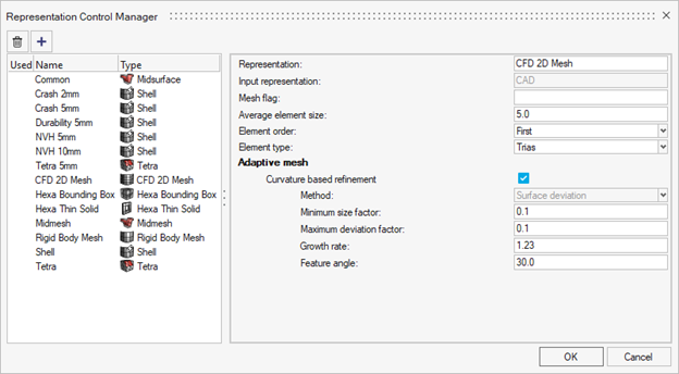
Figure 17. - A new automatic creation mode pairs a part’s PDM mesh flag with
the control's mesh flag to automate the creation process. This
ensures the right type of representations are created for the
right parts.

Figure 18.
- PDM Live Support for Windchill
- PDM live now supports Windchill integration. Now you can directly download/upload data from the HyperMesh Part Browser to Windchill.
- AMDC HyperMesh Integration
- You can log in and download materials from AMDC. This integration is available out-of-box, but you need AMDC log in credentials.
- Subsystem Instancing
- Subsystem instancing has been introduced allowing the duplication and repositioning of subsystems. Avoid making repetitive changes to multiple, identical subsystems by making the change once and using instancing and subsystem representations to load the same change in all instanced locations.
- Specify number of CPUs used by BatchMesher
-
- A new option was added to the preferences that you can use to define the number of CPUs allocated for BatchMesher operations.
- The default is to let HyperMesh automatically choose, as before,
but now you can manually select a specific number of CPUs to
use.

Figure 19.
Enhancements
- Library Manager
- The Library Manager’s updated layout allows for better organization and
overview of all libraries. It serves as a centralized hub for
registering and connecting all three types of libraries (Part,
Subsystem, and Material). For direct access to the Library Manager,
select the Libraries tool from the Assembly
ribbon.

Figure 20.
Figure 21. - Attribute Tables
- All available metadata associated with parts can now be listed in the Part Browser by adding new columns. To add a new column, from the entity editor right-click on specific metadata, and then select Add Column.
- Renumber
-
- The ordered selection for renumber was updated to use a specific
entity selector. You can now select ordered renumbering by
selecting a List option.

Figure 22. - The method to display IDs inside Renumber is now consistent with the method outside of the tool. Use with a selection made to show the IDs. The display of IDs is now passed correctly into and out of Renumber and Spatial Renumber contexts from idle.
- Any unresolved IDs are now shown in the text box inside the Renumber tool so you can see when these entities are not renumbered.
- The ordered selection for renumber was updated to use a specific
entity selector. You can now select ordered renumbering by
selecting a List option.
- Auto save Part representations
- When importing a monolithic geometry file, a single file that contains multiple parts, you no longer need to save representations for these parts before the creation process works. BatchMesher requires a representation file per part for input in the create work flow. When using a monolithic file, the representation is automatically saved when the representation name is assigned to the part, in session, when you try and create representations.
Morphing
Enhancements
- Morphing Release Highlights
- Watch this video to learn more about Morphing features in 2023.
- Panel Migration to Controllers
- is migrated under the Morph pull-down menu.
- Panel Migration to Context
- :
- Convert Forces to Shapes function is added as Create from Loads in the Shapes context menu. Access by right-clicking in the Edit Shapes dialog.
- Autoshape function is added in the Shapes context menu. Access by right-clicking in the Edit Shapes dialog.
- Smooth shapes function is added as Check/Smooth in the Shapes context menu. Access by right-clicking on shapes in the Edit Shapes dialog.
physicsAI
New Features
- Confidence Score (Beta)
- Informs how confident the model is in the prediction. Designs which are very different than the training data should receive low confidence scores.
-
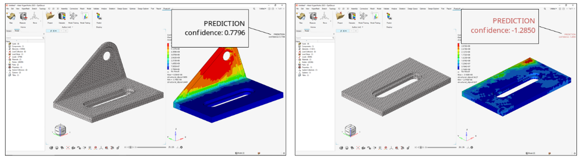
Figure 23. - Standalone App for Remote Training
- A standalone application which can be used to train physicsAI jobs remotely. This requires registering a training script in the physicsAI ribbon or in batch mode. Available on the AltairOne marketplace.
- Support for Solid Meshes
- physicsAI now supports solid meshes in two modes which can be toggled on
the dataset creation UI:
- Predicting on outer surfaces only (faster, default)
- Predicting results throughout the volume
-
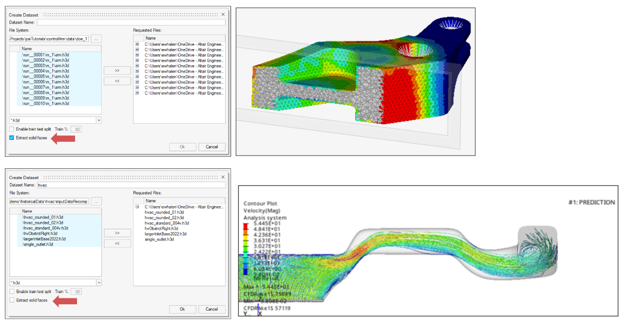
Figure 24. - Support for 2nd Order and 1D Elements
- All finite element types are now supported
Enhancements
- Faster dataset creation and smaller dataset file sizes
- More responsive UI
- Auto refresh model status and log for real time tracking
- Improved error message quality
Resolved Issues
- Predicting element-bound results (example, stresses and strains)
Announcements
- The “Validate with Solver” button has been retired
Known Issues
All tables are sorted alphabetically, even columns with numerical data, such as MAE. This can cause unexpected results, especially for values in scientific notation with varying exponents.
Post
New Features
- Post Release Highlights
- Watch this video to learn more about Post features in 2023.
- Free Body Section Context Menu
- A context menu is now available to create and edit free body section entities.
- The FBD Plot free body section is reconfigured.
- Mesh/infinite cut/finite cut to define a free body section either directly by elements and nodes or by a plane definition is now supported.
- Cross section entity support has been removed. Legacy files with free body section configuration "FBD Load" are converted to "FBD Plot" with support for infinite cut.
- Restrict intersected Comps/Parts to be considered.
- Improvement on interface node detection by plane are implemented. You can adjust detection playing with new plane thickness.
- You can review elements/nodes selected from a plane and convert
plane based sections into mesh based sections.

Figure 25.
Figure 26.
Figure 27.
Figure 28.
- Free Body Section Plot Context Menu
- Context menu to create, edit, and display FBD plots is implemented.
- Similar behavior to the contour/vector/tensor plots. It reacts to the active loadcase.
- Multiple plots can be created in the database.
- Plot components separately or plot normal/tangent resultants on a given
plane.

Figure 29.
Figure 30.
Figure 31.
Figure 32. - Entering free body section Edit mode with the plot active live updates
force extraction and display.

Figure 33.
Enhancements
- Memory Management
- Improved memory management on result query.
- Relative File Paths to Result Files
- This tool now works with relative file paths to result files.
- Free Body Tools Migration
- Force/Displacement and Cross section tools are removed.
- Use Create and Edit to generate free body sections.
- Use Plot control to generate force & displacement plots.
- Use the Manager to create
loads/fields/summary tables from free body sections.

Figure 34.
Figure 35.
- Browser Performance
- Improved browser performance when loading a large number of result files is implemented.
- Tooltips
- A large tooltip with a complete definition of each free body section is
available.

Figure 36. - Custom Category-based Legends
- A new type of category-based legend is supported. You can convert any
numeric result into categories and visualize it as a discrete,
range-based contour plot. For example, you can visualize a stress
contour plot as four categories by defining a custom category legend and
assigning it to the plot control.

Figure 37.
Resolved Issues
- Force/ Displacement /Cross section tools
- Several UI issue reported with these tools are fixed with new context menus.
- Improvement on interface node detection by plane (compared to legacy cross section).
- The "Copy legend" option, renamed to "Duplicate" in this release, now works as expected.
- Changing the marker color no longer affects the contour plot legend.
- The Legend position no longer changes when a deformed plot is applied (Linux only).
- The "Reset legend" option now resets all settings.
- Result plotting no longer fails when an input file is imported with "Create FE Geometry" ON in Solver Import Options.
- The application no longer crashes on contour plotting stress results from Nastran .hdf5 result file.
- CFAST element force vector is now displayed in the correct direction.
- Issue plotting element forces on CBUSH elements no longer occurs.
- Batch mode query no longer writes out an empty .csv when there are multiple result files.
- hm_getdatatypelayers API now points to HyperMesh subcase IDs rather than results IDs.
- hm_getsubcasedatatypes API no longer crashes when pointing to derived load case.
Safety Tools
No updates were made to Safety Tools in 2023.
Skeleton Modeling
Enhancements
Skeleton modeling has been updated so that it can take raw line data and reverse engineer the 1D reduced order model directly from FE or CAD. The capability is within the ABSORB function in the Skeleton ribbon, it will create the 1D mesh, beam sections, and sketches in one single step based on the initial line input.
Solver Conversion
Enhancements
- Abaqus to OptiStruct Conversion
- AXIAL,CARDAN Joint was converted to AXIACARD.
- Abaqus to Radioss Conversion
- HYPERELASTIC,MARLOW was converted to /LAW111
- LS-DYNA to OptiStruct Conversion
- *CONTROL TIMESTEP converted to NLEXPL
- Permas to OptiStruct Conversion
- MATERIAL,ANSIO was converted to MAT9.
- Radioss to OptiStruct Conversion
- /DT/NODA/CST converted to ANALYSIS NLEXPL
CAD and Solver Interfaces
Watch these videos to learn more about HyperMesh implicit and explicit solver interface updates in 2023.
Abaqus Interface
Enhancements
- A new element type MCL6 (cylindrical membrane elements) is supported.
- Keyword *CONTACT PAIR is enhanced to allow POSITION TOLERANCE when the ADJUST option is used.
- Keywords *CONTACT INITIALIZATION ASSIGNMENT and *CONTACT INITIALIZATION DATA are exposed to explicit profile in tandem with standard profiles.
- Migrated *COUPLING keyword to Constraints entity now supports HM binary files and Abaqus input files to retain component name as a prefix upon importing and opening in new versions of HyperMesh.
Resolved Issues
- R2D2 elements now honor the input file format for Abaqus on export.
- There is no longer an issue with contact group name retaining from binary files.
- Search of keyword *JOULE HEAT FRACTION is now available.
- In explicit profile, the create of *SURFACE INTERACTION now points to the correct keyword.
- Keyword DISPLACEMENT in *DYNAMICS TEMPERATURE-DISPLACEMENT is now spelled correctly.
- Time step calculation in explicit profile now considers direct property assignment.
- Beam section configuration change to SOLID and accessing 2017 binary files no longer results in a segmentation error.
- A regression from 2022.2 on comment entity to add comments to main file and include files now functions as expected.
ANSYS Interface
New Features
- Beam Meshing Tools
- Stiffener Mesh
- Mesh stiffeners are attached to shell elements. Support for Beam
(188&189) and Rod (Link180).
- Support mesh by proximity using free line but seeding nodes on the closest shells.
- Inherit orientation from the shell normal.
- Auto offset beams on top of the shell mesh.
- You can generate a stiffener on each edge of the source shell elements.
- The tool auto-generates the property SECTYPE and the associated
section (BEAM card) from the given beam section.
- You can leverage metadata beam section on parts holding free lines. These metadata are automatically created when importing Aveva Marine or OCX CAD formats.
- Mesh stiffeners are attached to shell elements. Support for Beam
(188&189) and Rod (Link180).
- Member Mesh
- Mesh lines/edges/node path with either Beam, Rod, or Pipe engineering configurations.
- Element type/section and property are created accordingly.
- Beam section types are filtered based on the desired configuration.
- for LINK180, the beam section area is directly mapped to
the to field area of the section entity.

Figure 38.
Figure 39.
Figure 40.
- for LINK180, the beam section area is directly mapped to
the to field area of the section entity.
- Beam Edit Tools
- The Align tool is used to adjust elements' n1→n2 order.
- Reorder nodes so the X-axis follows the closest global or local system axis in ascending order.
- The tool supports all types of beam elements.
- Offset
- Offset beams on the shell mesh.
- Assign offset keys: CENTROID/SHEAR CENTER/ORIGIN.
- Apply the same offset as a reference element.
- Apply incremental offset with a manipulator or set directly
offset components.

Figure 41.
Figure 42.
- Inflate
- Convert Beams to Surface and Shell Mesh
- Beam188 with either standard beam section or shell beam section.
- The tool creates surfaces from the beam section midline.
- Generate 2D mesh (SHELL181) with thickness assigned.
- Convert Beams to Solids
- Beam188 with a standard beam section only.
- Generate solid geometry from beams.

Figure 43.
Figure 44.
Enhancements
- Mapping real constants of the COMBIN39p property to a curve entity has been added.
CAD Interface
Enhancements
- Updated Version Support (Readers)
-
- JTOpen 11.2.3 library support is added.
- NX 12 native reader support dropped
Resolved Issues
- Fixed CATIA parameter reader related issues.
LS-DYNA Interface
New Features
- Contact Penetrations Check from Solver output files
-
- This new feature in the Penetration Check Tool allows directly reading the contact penetrations written by the solver in the messag or d3hsp files
- The penetrations are then populated in the Penetration Check Browser and fixed using the functionalities of the tool
- This new feature is activated by the new option "Check method"
in the Penetration Check Entity Editor

Figure 45.
- Time Step Mass in Mass Summary Tool
-
- A new option in the Mass Summary Tool enable the calculation of the solver numerical added mass due to the elemental time step
- From the guide bar, click
 and
select the Consider Time Step Mass
checkbox.
and
select the Consider Time Step Mass
checkbox.
Figure 46. - The corresponding Time Step Mass column and total values are
then display in the UI:

Figure 47.
- New Initial State Entity
-
- The INITIAL_STRESS_(OPTION) and INITIAL_STRAIN_(OPTION) keywords are migrated to the new Initial State entity
- The Initial State Entity is used to import and export the INITIAL_STRESS_(OPTION) and INITIAL_STRAIN_(OPTION) keywords, but not for creation or edition of the data in the session
Enhancements
- New Keywords supported
-
- Constrained Keywords: CONSTRAINED_SPR2
- Contact Keywords: CONTACT_2D_AUTOMATIC_(OPTION) and CONTACT_FORCE_TRANDUCER_ID
- Control Keywords: CONTROL_FORMING_TRIMMING, CONTROL_ACOUSTIC_SPECTRAL, CONTROL_ACOUSTIC_COUPLING, and CONTROL_IMPLICIT_SSD_DIRECT
- Material Keywords: MAT_SPRING_MUSCLE and MAT_EXTENDED_3-PARAMETER_BARLA
- Updated Keywords as per R13.1 manual
-
- Airbag Keywords: AIRBAG_PARTICLE
- Constrained Keywords: CONSTRAINED_NODAL_RIGID_BODY
- Control Keywords: CONTROL_ACCURACY, CONTROL_TERMINATION, CONTROL_SHELL, CONTROL_IMPLICIT_EIGENVALUE, and CONTROL_IMPLICIT_SOLVER, CONTROL_ADAPTIVE
- Database Keywords: DATABASE_BINARY_D3PLOT, DATABASE_BINARY_D3DUMP, DATABASE_BINARY_DEMFOR, and DATABASE_BINARY_INTFOR, DATABASE_EXTENT_BINARY
- Interface Keywords: INTERFACE_SPRINGBACK_(OPTIONS)
- Section Keywords: SECTION_SOLID
- Elements Entity Editor
- The description of the Elements Entity Editor is updated and aligned to the solver manual description
- Solver Mass Entity
- The node selector is activated in the entity table
Resolved Issues
- Drive Mapping now considers INCLUDE_PATH when defined in the deck
- ELEMENT_MASS defined on free node in old HM binary file are correctly converted to Solver Mass entity
- Correction of transformations calculation using POINT definition. Previous transformations are now correctly applied on the POINT coordinates
- Correction in reading MAT_SAMP-1 when followed by a PGP encryption block
- Correction of SET_PART_TREE format in exported deck, when more than 8 entities are referenced
- If the EC attribute is not used in MAT_FABRIC and it is defined in a deck, it will be read and maintained on export
- In Material keywords with AOPT attribute, if any attribute is defined but not compatible with the AOPT value, those attributes will be read and maintained on export
- Some entities, like Accelerometers, are automatically renumbered when an ID conflict is detected.
- Correction of the dynamic graphical update of CONSTRAINED_NODAL_RIGID_BODY when updating the secondary node set in case of SET_NODE_ADD
- Correction of graphical visualization of CONTACT involving PART of BEAM elements. The 3rd node of the beam is no longer taken into account
- SET_NODE referenced in CONSTRAINED_INTERPOLATION is no longer found as unused
- Model checker check "Tied contacts having common nodes" correctly considers only contact of type Tied
Nastran Interface
Enhancements
- Moved Non-structural Mass and Non-structural Material Damping Cards
- These cards are migrated from Group to Solver Mass entity.
- NSM1/NSM/NSML1/NSML bulk cards are now mapped to Solver Mass entity.
- NSMADD bulk data card is now mapped to Solver Mass entity.
- Loadstep Browser
- The Loadstep Browser is available in MSC and NX Nastran profiles.
- Model Checker
- Free 1D element nodes check is now available in the model checker.
Resolved Issues
- The CWELD card can now be edited.
- Component organization is no longer lost when importing input with includes created in previous releases.
- In the Beam Orient tool, orientation in displacement is streamlined.
- System selection and toggle basic/displacement to define orientation vector are removed from the microdialog. A direct option to enter components in the displacement system is available. A vector tool with user system selection to enter orientation vector is always in basic.
- The OFFT key assigned to elements when assigning orientation in the displacement system no longer has issues.

Figure 48.
Figure 49.
OptiStruct Interface
Enhancements
- SN Curve Plot Functionality
- Plot functionality exposed in the Model Browser material view for the MATFAT card defined with single/multiple SN curve definition.
- Static Failure
- The MATFAT and FATPARM cards are enhanced to input static failure definition for single/multiple curves in continuation to the SN line.
- Moved Non-structural Mass and Non-structural Material Damping Cards
- These cards are migrated from Group to Solver Mass entity.
- NSM1/NSM/NSML1/NSML and NSGE/NSGE1 bulk cards are now mapped to Solver Mass entity.
- NSMADD bulk data card is now mapped to Solver Mass entity.
- Multiple Failure Criteria Definition
- Multiple different failure criteria can be defined on a single MATF bulk card entry.
- New MATTVE Material Card
- A new material card MATTVE is added to define temperature-dependent nonlinear viscoelastic material.
- Model Checker
- Free 1D element nodes check is now available in the model checker.
- DENSITY Option in I/O Options
- A new DENSITY option is added in RTHRESH, THRESH, TOP, RTOP I/O cards.
- PBUSH and PBSUHT Cards
- The PBUSH and PBSUHT cards are enhanced to define KMAG and ANGLE continuation lines.
- SYSSETTING Card
- The SYSSETTING card is enhanced with a MULTIPLEOUTPUT option to define multiple formats of the same output request.
Resolved Issues
- The JOINTG element type INLINE is no longer imported as INLIORIE.
- Input files with DRAPE table no longer results in a segmentation error.
- The PCONT and PSOLID cards in large field format now export correctly.
- The MPF option is now available in the ERP card.
- Component organization is no longer lost while importing input with includes created in previous releases.
- In the Beam Orient tool, orientation in displacement is streamlined.
- System selection and toggle basic/displacement to define orientation vector are removed from the microdialog. A direct option to enter components in the displacement system is available. A vector tool with user system selection to enter orientation vector is always in basic.
- The OFFT key assigned to elements when assigning orientation in the displacement system no longer has issues.
Figure 50.
Figure 51.
PAM-CRASH Interface
New Features
- FE Joint Creation Tool
- The Joints tool enables the automatic creation of all types of FE Joints
(KJOIN, JOINT, MTOJNT, MBSYS_JOINT). The tool is located on the Model
Ribbon.

Figure 52.
Figure 53.
Enhancements
- Keyword Migration to New Entity
- NLAVE and RUPMO keywords are migrated from the Property entity to the Material Behaviors entity with Failure Configuration.
- Keyword Updates to PAM-CRASH 2022
- Control Cards:
- AUTOSLEEP, CKCTRL, ECTRL, EIGEN, ICTRL, PRCTRL, TCTRL, LACTRL, and OCTRL cards are updated with new fields as per VPS-2022 Solver manual.
- Mass Summary Tool
- Moment of inertia calculation is now inline with Solver calculation.
Resolved Issues
- Component ID (IDPRT) Parametrization is also applied to associated Elements on exported deck.
- For THELE and THLOC, after the creation of one keyword, the other keyword entity is removed.
Radioss Interface
New Features
- Support of the new Radioss 2023 profile
- Joint Creation Tool
-
- This new tool enables the automatic creation of KJOINT2 and CYL_JOINT elements, as well as the rigid attachments of the joint to the selected connected parts
- The tool is accessible from the Model Ribbon:

Figure 54.
Figure 55.
- Time Step Mass in Mass Summary Tool
-
- A new option in the Mass Summary Tool enable the calculation of the solver numerical added mass due to the elemental time step
- From the guide bar, click and
select the Consider Time Step Mass
checkbox.
Figure 56. - The corresponding Time Step Mass column and total values are
then display in the UI:
Figure 57.
Enhancements
- New Starter Keywords supported
-
- /EOS/TABULATED
- /FAIL/INIEVO
- /FAIL/SYAZWAN
- /FAIL/TAB2
- /SENSOR/TEMP
- /TRANSFORM/POSITION
- New Engine Keywords supported
-
- Multiple new output options supported in /H3D/ELEM
- Multiple new output options supported in /H3D/NODA
- Multiple new output options supported in /H3D/SHELL
- Multiple new output options supported in /H3D/SOLID
- Updated Starter Keywords as per Radioss 2023 manual
-
- /BEAM: 3rd node made optional
- /INTER/TYPE8: New attribute Fn_last and Ft_last
- /INTER/TYPE18: New attribute Igap
- /MAT/LAW62: New attribute Form and Poisson ratios
- /MAT/LAW88: New attribute value Tension=-2
- /PROP/TYPE14: New attribute Iale
- /RBODY: New attribute Ifail
- /SENSOR/DIST: New attribute Tmin and Dflag
- Support on nested SUBMODELs
- Elements Entity Editor
- The description of the Elements Entity Editor is updated and aligned to the solver manual description
- Rigid Body Manager
- The Rigid Body Manager is replaced by the new Rigid Body creation controller
Resolved Issues
- Correction in reading the Engine keywords /DT/AMS
- Correction of the dynamic graphical update of /RBODY when modifying the node set in case of a formula set
- Correction in reading /VISC/PRONY when the keyword is encrypted
- Correction in reading and exporting Area and Inertia attributes in /PROP/BEAM when Beamsection is Unresolved
- In some cases, /GRNOD/NODE referred into /INTER keyword was exported as an empty /GRNOD/GENE set. This issue is now corrected.
- CYL_JOINT is now implemented correctly.