Oscillating Laminar Flow Around a Circular Cylinder
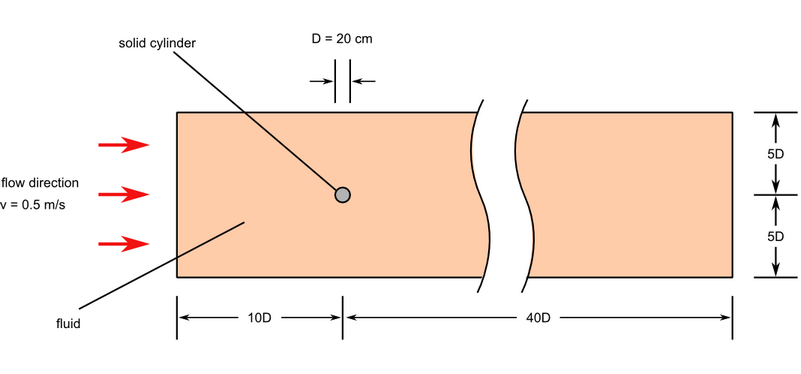
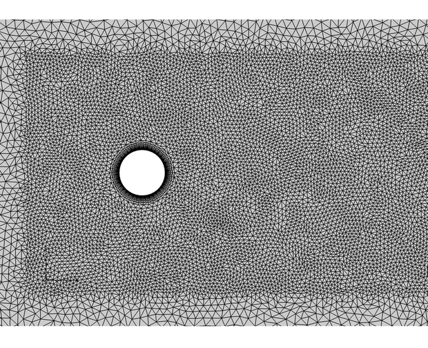
In this application, AcuSolve is used to simulate two dimensional, laminar flow over a cylinder to predict separation of flow from the cylinder surface and the flow in the wake area. AcuSolve results are compared with experimental results as described in Tritton (1959). The close agreement of AcuSolve results with experimental results validates the ability of AcuSolve to model cases with unsteady oscillating vortex streets.
Problem Description


AcuSolve Results


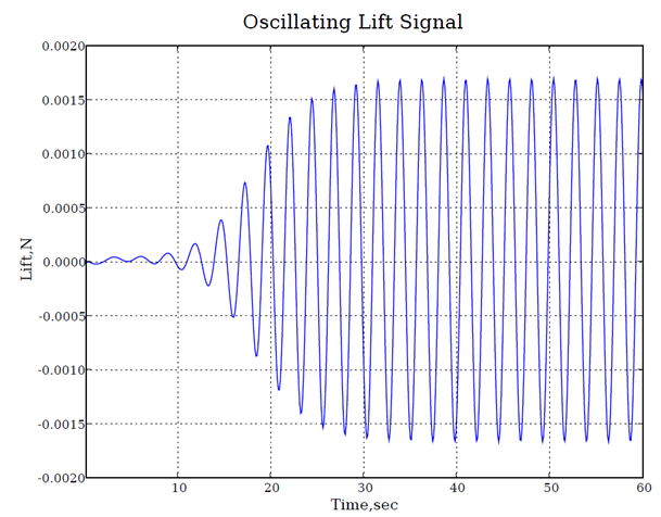
The Strouhal number for this simulation, a dimensionless number describing oscillating flows, is used to validate AcuSolve results. The experimental Strouhal number for this problem is given by
where ω is the dominant frequency of oscillations, L is the diameter of the cylinder, and v is the flow velocity.
| Experimental | AcuSolve | |
|---|---|---|
| Strouhal number | 0.165 | 0.173 |
Summary
In this application, two dimensional flow over a cylinder is achieved by enforcing symmetry conditions on the front and back surfaces of the flow domain. The laminar, unsteady simulation shows the flow separation that leads to alternating vortex shedding. Frequency of the lift force acting on the cylinder is calculated to evaluate the Strouhal number. The AcuSolve solution compares well with results reported by Tritton (1959), differing slightly from the experimental results. In this application, AcuSolve demonstrates the ability to accurately predict oscillating laminar flow around a circular cylinder.
Simulation Settings for Oscillating Laminar Flow Around a Circular Cylinder
HyperMesh CFD database file: <your working directory>\cylinder_laminar\cylinder_laminar.hm
Global
- Problem Description
- Analysis type - Transient
- Turbulence equation - Laminar
- Auto Solution Strategy
- Analysis type - Transient
- Max time - 600 sec
- Initial time increment - 0.1 sec
- Material Model
- Fluid
- Density - 1.0 kg/m3
- Viscosity - 1.0e-3 kg/m-sec
Model
- Fluid
- Volumes
- Volume
- Element Set
- Material model - Fluid
- Element Set
- Volume
- Surfaces
- Back
- Simple Boundary Condition
- Type - Symmetry
- Simple Boundary Condition
- Base
- Simple Boundary Condition
- Type - Slip
- Simple Boundary Condition
- Front
- Simple Boundary Condition
- Type - Symmetry
- Simple Boundary Condition
- Inflow
- Simple Boundary Condition
- Type - Inflow
- Inflow Type - Average velocity
- Average Velocity - 0.5 m/sec
- Simple Boundary Condition
- Outflow
- Simple Boundary Condition
- Type - Outflow
- Simple Boundary Condition
- Top
- Simple Boundary Condition
- Type - Slip
- Simple Boundary Condition
- Back
References
D.J. Tritton. "Experiments on the Flow around a Circular Cylinder at Low Reynolds Number". Journal of Fluid Mech. 6(04):547-567. 1959