Scheme
Overview
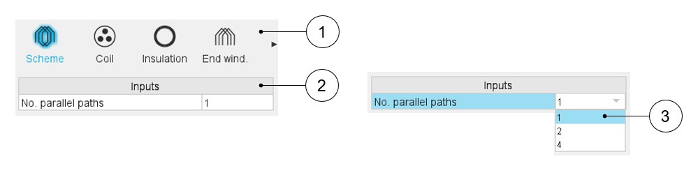
Here are below the winding scheme user inputs.
 |
|
|---|---|
| 1 | Sections to design the winding step by step. |
| 2 | List of user inputs to define the winding architecture. One user
input to be defined: the number of parallel paths. Note: The possible numbers of parallel paths
are automatically computed and proposed to the user (3). When the user selects the number of parallel paths, the connections on the field winding scheme are automatically updated |
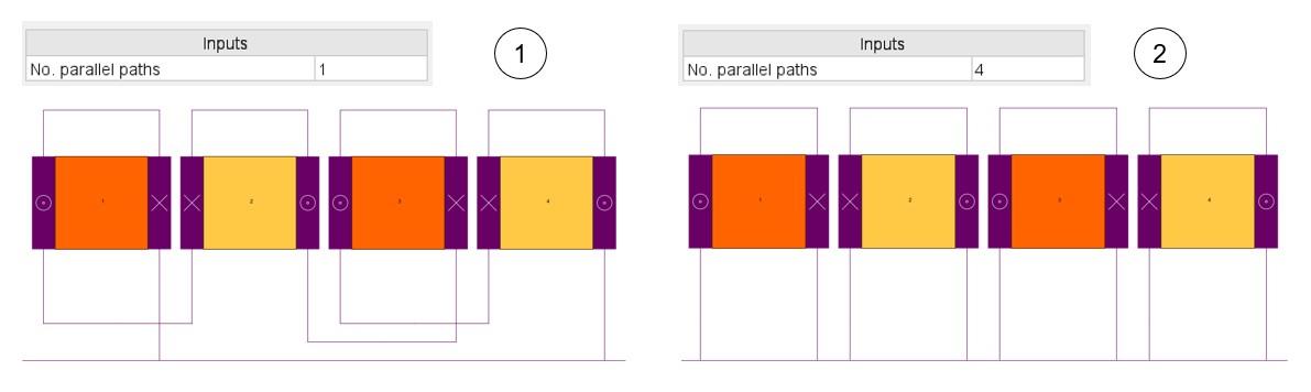
Parallel paths
 |
|
|---|---|
| 1 | Example where the No. parallel paths is equal to 1 |
| 2 | Example where the No. parallel paths is equal to 4 |