Coil
Description
 |
|
|---|---|
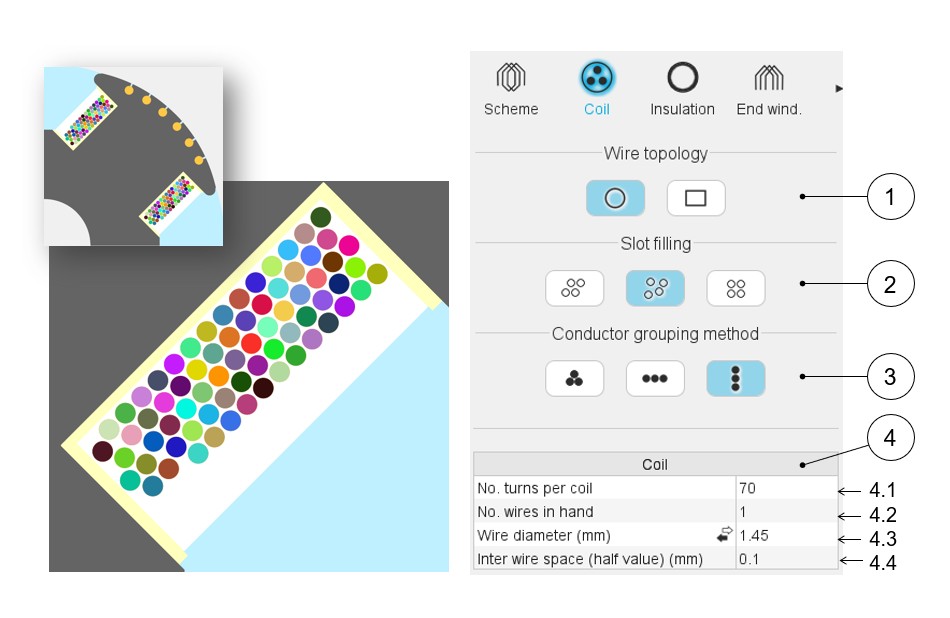
| 1 | Definition of the wire topology, Circular or Rectangular |
| 2 | Choice of the method to fill the slot: Three ways are allowed to fill the slot: Orthocyclic, Random, Layer. See the below illustrations. |
| 3 | Choice of method to group the elementary wires. Three ways allow to fill the slot: Grouped, Horizontal, Vertical. |
| 4 | Description of the coil and dimensions of elementary wires + twist options |
| 4.1 | Number of turns per coil |
| 4.2 | Number of wires in parallel in a conductor (per turn) i.e., number of wires in parallel in each conductor |
| 4.3 | Wire dimensions - Diameter (without insulation) (1) |
| 4.4 | Minimum distance between insulated wires to be considered for
modelling inside the Flux® 2D environment. When there is no wire insulation, Inter-wire space represents the minimum distance between the bar wires (2). |
Note: Different ways are available to choose the wire diameter:
- Directly entering the value of the wire diameter (without insulation)
- Choose the diameter from the American Wire Gauge table in which available wire diameters are listed (without insulation)
- Choose the diameter from the Metric Wire Gauge table in which available wire diameters are listed (without insulation)
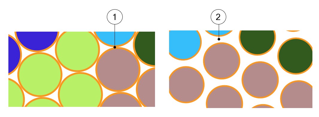
Note: Illustration of inter-wire space
This value is considered in the Motor factory for computing the filling factor and while exporting a model into Flux® environment (Export area) for building the corresponding finite element model.
 |
|
|---|---|
| 1 | Default value for inter-wire space and the corresponding pictorial display |
| 2 | Impact of a higher value for inter-wire space |