Depuis la version 2026, Flux 3D et Flux PEEC ne sont plus disponibles.
Veuillez utiliser SimLab pour créer un nouveau projet 3D ou pour importer un projet Flux 3D existant.
Veuillez utiliser SimLab pour créer un nouveau projet PEEC (pas possible d'importer un projet Flux PEEC existant).
/!\ La documentation est en cours de mise à jour – des références au 3D peuvent subsister.
Flux dans SimLab : Exemples 2D et Skew
Exemples 2D
| Solution | Exemple | Description | Illustration |
|---|---|---|---|
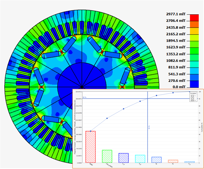
| 2D Transient Magnetic |
Brushless IPM motor | The studied device, a brushless AC embedded permanent magnet
motor presented in the figure in the right, includes the
following elements:
|
 |
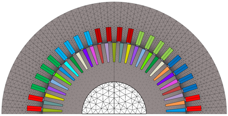
| 2D Transient Magnetic |
Brushless SPM motor |
The studied device, a brushless DC motor with surface permanent magnet, includes the following elements:
|
 |
| 2D Transient Magnetic |
Multi-physics (EM, NVH, CFD) Analysis of a 75 kW PMSM - Motor Mode |
The studied device, a 75-kW permanent magnet synchronous
machine, is running in motor mode. As presented in the figure in
the right, it includes the following elements:
|
 |
| 2D Transient Magnetic |
EM-CFD Coupling Analysis of a 75 kW PMSM (Air Cooling) - Generator Mode |
The studied device, a 75-kW permanent magnet synchronous
machine, is running in generator mode. As presented in the
figure in the right, it includes the following elements:
|
 |
| 2D Transient Magnetic | Synchronous Reluctance Motor (SynRM) | The studied device, a synchronous reluctance motor, is
running in motor mode. As presented in the figure in the right,
it includes the following elements:
|
 |
| 2D Transient Magnetic | Wound Field Rotor Motor | The studied device, a wound field synchronous motor, is
running in motor mode. As presented in the figure below, it
includes the following elements:
|
 |
| 2D Transient Magnetic | MT2D - Wound field Machine 75kW (EM part) | Modelization of a Synchronous Machine with Wound Field – Inner Salient Pole - Inner Rotor , comparable to IkerMAQ 75 kW PMSM. |  |
| 2D Axi Transient Magnetic | Actuator | The studied device includes the following elements:
|
 |
| 2D Transient Magnetic | DOE and optimization for PM motors |
The goal is to optimize the base point of the motor
The optimization is done by HyperStudy. |
 |
| RMM solution (MT2D) | Impact of PWM losses for PM motors |
This study case analyzes the effect of the harmonics in PWM currents on an eMachine. The workflow is :
These TM results can then be used in an NVH or CFD simulation to analyze the effect of PWM harmonics on the motor multiphysics. |
 |
| 2D AC Magnetic | Induction Motor | The studied device, an induction motor presented in the figure in the right, includes the following elements:
|
 |
| 2D Transient Magnetic | Multiphysics (EM-CFD): 2-way coupling for eMotor air cooling analysis | This study case will present how to use the new EM-CFD 2-way coupling solution in SimLab to model and analyze an eMotor air cooling process. |  |
Exemples Skew
| Solution | Exemple | Description | Illustration |
|---|---|---|---|
| SKEW Transient Magnetic | PMSM with a step-skewed rotor |
The studied device, a permanent magnet synchronous motor (PMSM) presented in the figure in the right, includes the following elements:
|
 |
| SKEW Transient Magnetic | PMSM with a continuous-skewed stator |
The studied device, a permanent magnet synchronous motor (PMSM) presented in the figure in the right, includes the following elements:
|
 |
| SKEW Transient Magnetic | Multiphysics (EM-NVH): step-skew multispeed | This study case will present how to run a multi-speed EM-NVH analysis of an eMotor with rotor step-skewing. First, the motor is electromagnetically modeled and analyzed using the MTSkew solution. Then, the electromagnetic force at each speed is imported into the 3D motor model and analyzed using the MFR (modal frequency response) solution to get the waterfall plot. |  |