Motor End Space
Description
Flow Simulator uses a variety of heat transfer correlations to model the heat exchange phenomenon in flow and thermal networks.
The correlation types available with Flow Simulator to model convection heat transfer in internal components of an electric motor are discussed below.
Motor Component Internal Cooling
- (i) Generic Motor Component Heat Transfer
- Used to model heat exchange between different motor components such as rotor, magnet, stator, windings, shaft, housing and so on, and the internal fluid.
- Type
- Motor Comp Internal NU
- Subtype
- Motor Endspace Convection
| Index | UI Name (.flo label) | Description | Mandatory/Not Mandatory |
|---|---|---|---|
| 1 | Component Category (COMP_CAT) | The component category has five options based on the motor
parts, in between which the convection heat transfer need to be
modeled:
|
Mandatory The motor component category decides the correlation coefficients to be used in the calculation. See the Formulation section for more details. |
| 2 | Fluid Region (REGION) | Fluid Region has two options based on the location of the
convector inside the motor:
|
Mandatory The fluid region decides the tip speed ratio, which in turn is used to deduce the velocity of the fluid. See the Formulation section for more details. |
| 3 | Mode of Convection (MODE) | Mode of convection has two options based on the type of
convection that needs to be modeled:
|
Mandatory The type of convection sets up the tip speed ratios automatically to deduce the velocity of fluid near the motor components. |
| 4 | Rotor Conductor (ROT_COND) | The conductor ID that represents the rotor. On specifying a valid rotor conductor ID, Flow Simulator automatically retrieves the rotor dimensions. |
Mandatory If there is no rotor conductor existing that can be used to retrieve the rotor dimensions, this input can be left as 0, and the rotor dimensions can be entered in subsequent inputs. |
| 5 | Rotor Inner Radius (RIR) | Inner radius of the rotor. | Mandatory If you have provided a valid rotor conductor ID that can be used to retrieve Rotor Inner Radius, this can be left as AUTO. If you have left the rotor conductor input as 0, then user must enter a rotor inner radius. |
| 6 | Rotor Outer Radius (ROR) | Outer radius of the rotor. | Mandatory If you have provided a valid rotor conductor ID that can be used to retrieve rotor outer radius, this can be left as AUTO. If you have left the rotor conductor input as 0, then you must enter a rotor outer radius. |
| 7 | Fluid Velocity (FLOW_VEL) | Fluid velocity in the specified region. | Mandatory If the selected mode of convection is forced convection, and you want the Flow Simulator solver to calculate the velocity using rotor dimensions, RPM, and tip speed ratio, the fluid velocity option should be left as AUTO. Otherwise, if you want to enter your own velocity values, you can clear the AUTO option and enter the velocity. If the selected mode of convection is natural convection, the Flow Simulator solver uses the tip speed ratio to determine the fluid velocity, so in this case, this option should be left as AUTO. |
| 8 | Tip Speed Ratio (TIP_SPD_RAT) | Tip speed ratio for the specified region, used in the calculation of the fluid velocity. | Mandatory If the tip speed ratio is set to AUTO, the Flow Simulator solver assigns the tip speed ratio based on the type of convection and motor component as per Table 3 in the Formulation section. If you want to enter your own tip speed ratio for any configuration, you can clear the AUTO option and enter the tip speed ratio. |
| 9 | HTC Multiplier (HTC_MULT) | A constant multiplier to scale the value of heat transfer coefficient obtained from the correlation. | Not Mandatory Default value is 1.0. |
Formulation
The expression for the heat transfer coefficient for the motor internal components convection is given as (Ref. 1):
Where, is the peripheral rotor speed in m/s.
| Components | k1 | k2 | k3 | Reference |
|---|---|---|---|---|
| Housing-End Space Fluid | 20.0 | 8.7 | 0.7 | 1,2 |
| Winding-End Space Fluid | 15.0 | 6.0 | 0.9 | 1,2 |
| Rotor-End Space Fluid Stator-End Space Fluid Shaft-End Space Fluid |
41.4 | 6.22 | 1.0 | 3 |
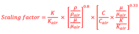
The scaling factor is then multiplied to the heat transfer coefficient as:
| Component Location in Motor | Type of Convection | Tip Speed Ratio |
|---|---|---|
| Upper (Frame Side) | Forced | 2.0 |
| Lower (Shaft Side) | Forced | 1.5 |
| Upper (Frame Side) | Natural | 5.0 |
| Lower (Shaft Side) | Natural |
The updated velocity is:
| Index | .flo label | Description |
|---|---|---|
| 1 | TNET | Thermal network ID, which has the convector where this correlation is used. |
| 2 | CONV_ID | Convector ID, which is using this correlation. |
| 3 | CATEGORY | Component category using this correlation. |
| 4 | REGION | Fluid region in the motor using this correlation. |
| 5 | MODE | Mode of convection. |
| 6 | ROT_OUT_RAD | Solver calculated/auto-retrieved rotor outer radius for the model. |
| 7 | FLOW_VEL | Fluid velocity calculated/auto-retrieved for the model. |
| 8 | TIP_SPD_RATIO | Tip speed ratio calculated/auto-retrieved for the model. |
| 9 | K1, K2, K3 | Coefficients for the correlations. |
| 10 | Scale_Fac | Scale factor calculated for the model. |
| 11 | HTC | Heat transfer coefficient calculated as per the correlation. |
References
- Peer-Ole Gronwald and Thorsten A. Kern, "Traction motor cooling systems, a literature review and comparative study", IEEE Transactions on Transportation Electrification 2021. DOI: 10.1109/TTE.2021.3075844.
- Micallef, Christopher, "End winding cooling in electric machines", Ph.D. dissertation, Available: http://eprints.nottingham.ac.uk/id/eprint/10260.
- Boglietti and Cavagnino, “Analysis of the Endwinding Cooling Effects in TEFC Induction Motors", 2007 (doi: 10.1109/TIA.2007.904399).