Pattern Sharp Angle
This rule searches for routing angles that are sharper than the specified reference angle.
While it is unavoidable to bend traces in most PCB designs, sharp bends cause
problems in both performance and manufacturing,for example, trace reflection, EMC
failure and acid trap. During routing, routing angle less than 90 degrees behaves as
capacitive discontinuity so it may make nearby signal nets’ distortion or coupling
noise. The sharp point at the corner will enlarge the electrical
field.
- Item: Input item name.
- Net: Select a target net group.
- Exclude Net: Exclude net group by net group name. Normally, the Power and Ground net should be excluded.
- Condition: Specify a sign of inequality for check pattern angle.
- Angle: Assign a reference angle.
- Ignore Short Pattern: The trace shorter than this will be ignored.
- Pin Escape: Enter a radius of circular region around pins to be excluded for the rule check.
- Long Straightened Pattern Check: Check if signal trace straightened longer than this value.
- Copper Boundary Line Width Check: Check the boundary line width of polygon. If boundary line width equals zero, it reports as failed.
Effects of Sharp Angle Bend
- Reflections
- Primarily due to change of width at the corner (1.414 times increase at the apex for 90-degree bend).
- Upsets the transmission line characteristics, especially distributed capacitance and self-Inductance.
- Acts like a capacitive load attached to the transmission line.
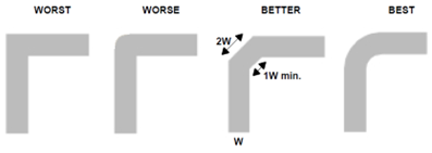
- Rounding the bend with a constant width reduces reflection and rise-time. Simpler to chamfering the corner to 45 degrees.
- EMC Failure
- At high frequencies, the sharp corners may cause EMC failure.
- Acid Trap
-
Sharp corners tend to retain enchant during the PCB manufacturing process.
- Etching in sharp corners becomes difficult to rinse and can cause delayed action of etching.
- For narrow traces, over-etching on the inside of the bend eats away
a higher percentage of the available copper than for wider
traces.
Figure 1. 
-